German S-100 Class Schnellboot (Fast Boat)
The SBoot Torpedo and Torpedo Tube
Again, like the Hull-2 project, progress becomes very slow as much research is needed on every part to get the dimensions and details right.
The completed and operational G7A torpedo with shapeways printed warhead and tail bodies, whiskers, impeller and tail fin assembly, the mid body is 26mm OD (24mm ID) carbon fibre tube cut to length and painted silver. The propellers are my USN Mk13 solid silver props and the latest printed circuit board, the body parts are not painted yet. This is also fitted with my latest crosshead part, holding the crown gears in place, with M2 nylock nuts, this seems to work well but is made from the wrong material which will probably break, this has tiny detail and couldn't be made out of the black Nylon type material, I shall try getting it cast in silver or bronze but as I said it is tiny. The mid body could also be made from rigid PVC conduit or pipe, in the USA you have 3/4" class 200 pipe which is almost the perfect size, OD is 1.05" or 26.67mm and the ID is 0.93" or 23.62mm, The front and rear bodies are made to fit 24mm or 0.945" so would need some sanding internally, in Australia we have 20mm white communications conduit that is the same size.
This shows the new crosshead, this piece and two M2 nuts replaces two laser cut crosses and four long M2 screws and this is easier to put together.
Below are some virtual created images from my new 3D G7A torpedo models which I will get 3D printed as soon as I can.
I have made up the USN Mk13-1 torpedo body at 1/20th scale and I also have a 1/35th version of that on it's way as well as a USN Mk14 set and I will be making up the Mk13-0 and Mk13-2 and the Mk8 and Mk15 as I progress, my plan is to put these all up on shapeways so that you guy's can purchase them from there, scales will be 1/20th to start and I may do some other scales based on demand.
The Front Body
The Tail Section and Fin Assembly
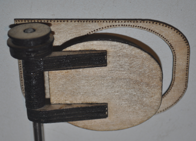
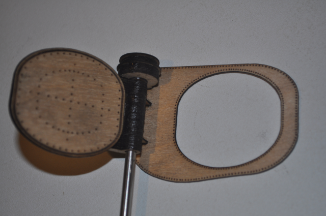
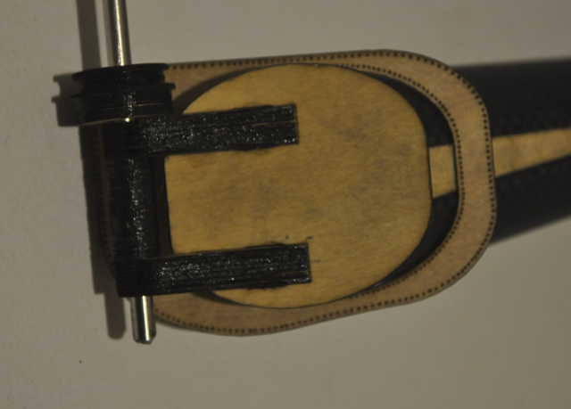
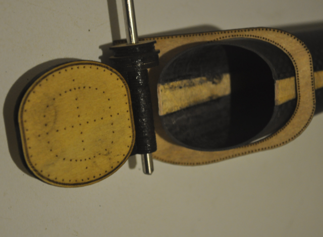
The Whiskers and Spinner
The purpose of the Whiskers and Spinner assembly is to stop the torpedo from detonating until it has travelled some distance in the water, the propeller acts to wind out the whiskers and thus ARM the detonator"
I have done battle with a few 3D cad programs and I am not impressed with many of them however I played with Autodesk's Fusion 360 for a few days and managed to get to version 33 of the G7A main body as a learning excercise before I got it the way I wanted and got rid of the really annoying unwanted hole that would not go away. I have even made the front arming spinner that should spin properly and the detonation whiskers in the armed position. I have made the rear propeller cage assembly with all it's rivets and rudders and it is a separate assembly so that it can be fitted after the propellers are inserted. I did this because the new torpedo has so much grunt that the silver propellers will need to be soldered to the brass drive shafts to stop them falling off and this then requires that I can slide the drive shafts into position before fitting the cage, I have made 4 slots in the body for it to fit in. The front of the warhead has a depression in the front for the whisker's assembly to fit into.
This is the almost finished torpedo body, I am working on the inside currently, I have batteries, motors, speed controllers etc.
This is resin front and rear with a carbon fibre mid body.
Below is my version of the German WW2 G7a or G7e Torpedo drawing:
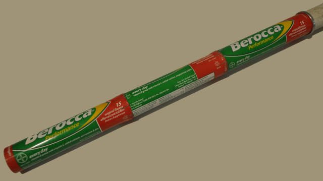
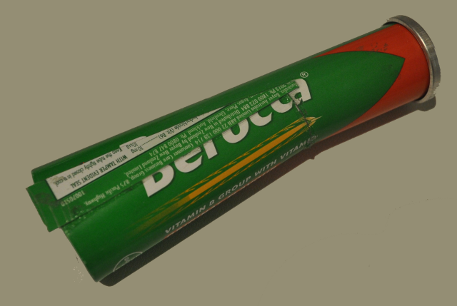
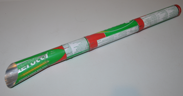
The German G7a and later G7e Torpedo were both 21" (533.4mm) diameter, which is exactly the same diameter as the US and British "long" torpedo's, so for the model at 1/20th scale it can also be made from 20mm (26mm OD) communications conduit and this will fit perfectly into a "Berocca" (Vitamin B) aluminium tube, the same as the first torpedo's that I produced for Hull-1. Note: July 2017, I now have Carbon fibre tube the right size for building 1/20th scale torpedo tubes!
I have also purchased a number of tiny brushless motors and a couple of tiny ESC's to drive them, I have more bouyancy in these longer torpedo's so I can add some extra weight, I estimate around 200grams all up displacement. I need to make a nose and tail section and use carbon fibre tubing for the middle body section. I am very impressed with the quality, thin wall, strength and lightness of the carbon fibre tubing.
The torpedo tail section presses into the carbon fibre tube, In my first models I was trying to make the torpedo sections screw together but this is unnecessary as the forward thrust of the props keeps it together anyway , it just needs to be a fairly tight fit with a little vaseline as a water seal (once it's painted of course).
The torpedo front section, I have added the firing mechanism as a prop and "whiskers" in the retracted position as I need to be able to easily mould this without breaking the whiskers off.
The propellers in place, these are the same props as my US Mk13 torpedo and again are cast in solid silver.
A side view of the counter rotating props, in the US Mk13 these work extremely well so I expect the same, so far I have done a small test in the sink and looking good! You can see that the central hubs are tapered and the rear prop is smaller in overall diameter than the front one, the blades are all the same size however.
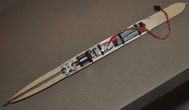
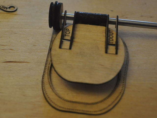
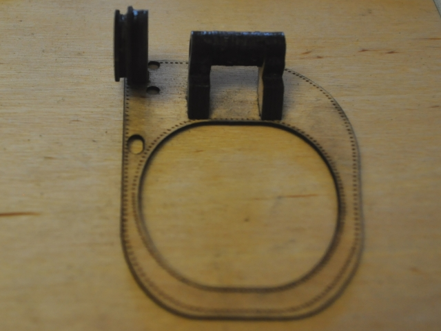
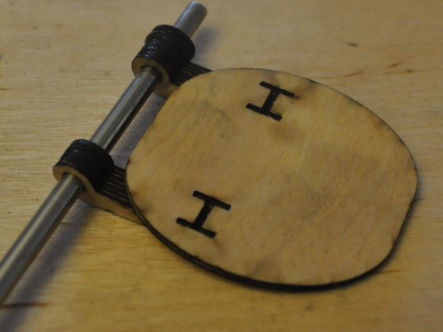
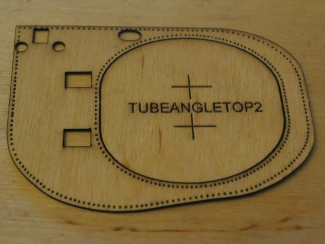
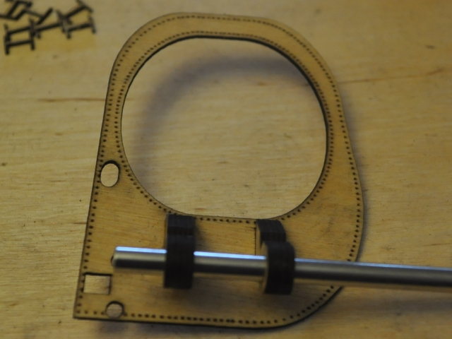
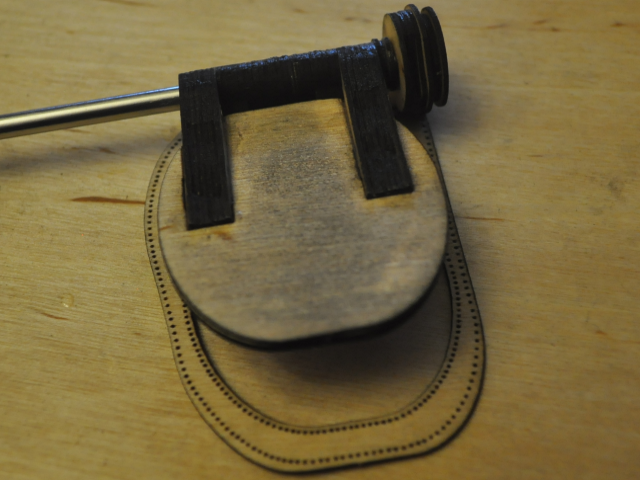
This is the first draft of the torpedo's inside prototype setup, made from lasercut ply, a revised version of my famous gearbox, a small brushless outrunner motor, a tiny ESC and two Turnigy Nanotech 270mAH Lipo cells (7.4Volts). I tried 4 cells and it would seem to be too fast so I am proceeding with two only, I was planning on two cells on the other side of the board as well but maybe that will become a servo and tiny receiver instead. My current plan is to make up a multivibrator circuit using a cmos 555 timer to pretend to be the receiver, so that I can operate the speed controller without a receiver. I can then add a potentiometer to control the motor speed from inside the torpedo. The standby current when the receiver signal is disconnected is only around 10mA so I have put a small strapping plug (or maybe it will end up as a switch) to disconnect the battery's to stop them draining. So the proposed proceedure would be remove the torpedo's front body, switch on the torpedo and load it into the torpedo tube(s) The internal magnetic reed switch only then needs to control the input to the speed controller rather than the full motor current and will save some big transistors. With the switch or strap in the "ON" position these battery's can supply 10mA for around 27 hours which should be enough time for fun! I will also provide for a connector for balance charging the two (or maybe three) cells.
The biggest issue with torpedo's is that they must not have any body roll or they will wander all over the place, I'm sure Mr Whitehead had the same issue a hundred years ago, so counter rotating propellers are a must have. I tried a gearbox in my very first counter rotating torpedo but the friction losses were too much for the DC magnet motors and limited voltage that I could fit in and the gearbox was also hard to make, so I abandoned the idea in favour of two motors but with brushless outrunner motors there is so much more torque from a much smaller device and I have spent maybe 15 years thinking about how to make a simple "makeable" gearbox.
There is much more bouyancy in this beast, I am going to have to fill it with weights, which is great because it will be much easier to balance, the old Mk13 one needed to be spot on for balance as it was just a smidge too heavy!
More to come, of course, and you won't be disappointed!
For the 1/35th scale I have bought an available resin kit model, this was actually a Mini Submarine model from Verlinden made up of two German torpedo's with the top one having a perspex bubble on the front (warhead section) where the pilot would have been, so I cut and filed this off and made up two almost identical regular torpedo models.
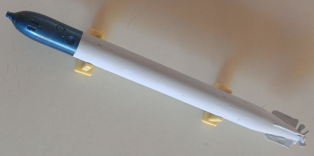
I have painted this with a very light grey matt paint (Humbrol 147) and a metallic blue paint (Tamiya X-13) for the warhead. I used some cellotape as masking tape wrapped around the body to get the line straight between the two colours. My only criticism of this kit is that the fins and prop blades end up larger in diameter than the main torpedo body which isn't correct and wouldn't work in a torpedo tube, however I am not planning on launching these, they will be just mounted on the deck so it doesn't matter.
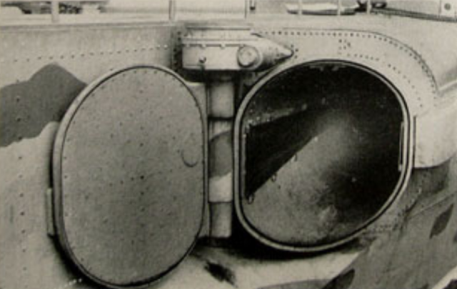
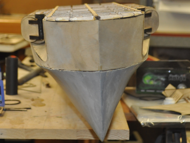
This photo shows the later Schnellboot model S100 torpedo door fully open, it also shows how the lower part of the torpedo tube slopes downwards at the opening (probably to prevent the prop blades from hitting the tube on the way out) and the complex shape that is produced when this is cut at 45 degrees.
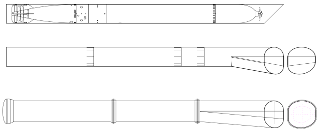
Here are a couple of drawings of the torpedo tube, the bottom one is the type of tube used on the earlier open forecastle style of SBoot and one can only assume that the S100 series with a higher covered forecastle torpedo tubes were the same shape, although we know that for the S100 the door opened sideways as in the photo above and didn't open up to the top of the tube as in the earlier versions, which seems a bit of a mistake in design as it would have blocked the torpedoman's view.
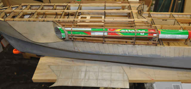
The middle tube drawing is my proposed "Berocca" tube for the 1/20th scale boat, the berocca tubes have the expanded open end cut off and all but one has the bottom blocked end cut off as well. Then 8 slits are cut at all 45 degree points around the tube back about 10mm from the cut end, this allows the tube to be expanded to fit over the next tube behind it. the opening door end is also split for about 80mm (3") lengthwise horizontally and then a thin wedge is cut almost all the way through from the bottom side so that it can be peeled open at the required angle. I then glued some triangular pieces of flattened tube over the created triangular openings and glued them on both sides with "Loctite" brand superglue. once this was allowed to fully dry I cut the end of the tube at 45 degrees. I glued all the tubes together with a long piece of 20mm communications white pvc conduit inside to keep it all in line and make sure the torpedo can slide easily all the way through.
This shows 3 Berocca tubes glued together with a piece of conduit inside to keep it straight.
This picture shows the lengthwise split tube with a flattened piece of tube material glued over the triangular gap.
Another view of the finished split showing the ends.
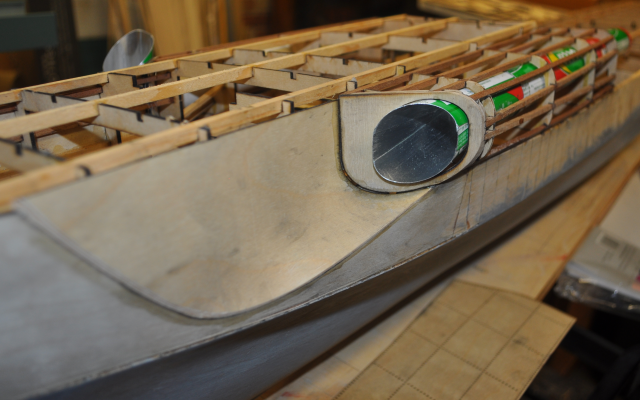
This is what the 45 degree torpedo door end will look like. Notice that the outside wedge is not as high as the inside wedge due to the 45 degree cut, this is what makes the bottom shape such a headbutt to workout, as it isn't just a semicircle.
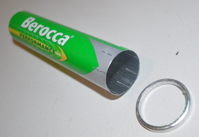
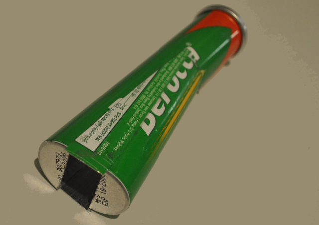
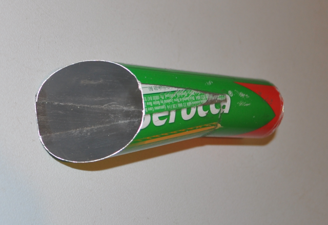
To join the tubes together, cut the end off the tube with a small hobby saw and cut 8 slits around the tube circumference, so it will fit over the next tube. Then cut off the closed end for the intermediate tubes. You also need to clean up the ends to get rid of any burrs.
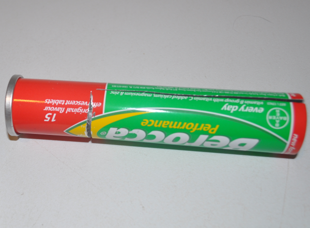
I split the tube longways with a small hobby saw and cut a wedge out on one side, not quite all the way through to the split, so that it stays together.
This shows the tube opened out ready to glue the side wedges on. I used "Loctite" brand superglue.
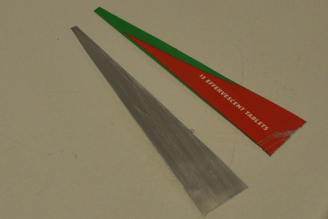
This shows the two side wedges cut from flattened pieces of tube, the Berocca tube is only around 0.25mm thick and is easily cut with scissors. You can rub the tube with a flat piece of plastic or something on both sides on a flat surface to get it flat and straight.
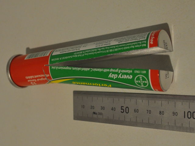
One of the torpedo tubes finished, these are 400mm long. Now I need another one with the opposite cut. These are actually easier to make than I expected. I have been saving these tubes for years expecting to wreck a few in the process but with the right saw it is a fairly easy task.
Port side tube in place and showing the tube covering below, complete with rivet markings.
Port tube in place.
Now - how to make the torpedoes fire out of the tubes?
I bought some 4mm high pressure air tube and air fittings and did some testing to see how much air pressure is needed to launch a torpedo, 25 PSI (2 Bar) will probably be just enough but at 100 PSI the torpedo flies out of the tube, I'll post some pictures when I've built something more like a real torpedo but I am very pleased with all the work!
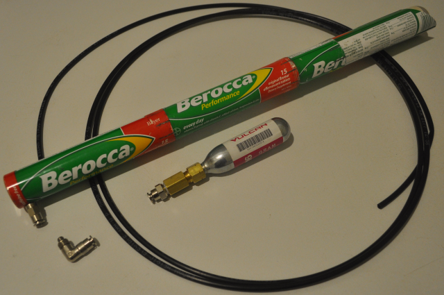
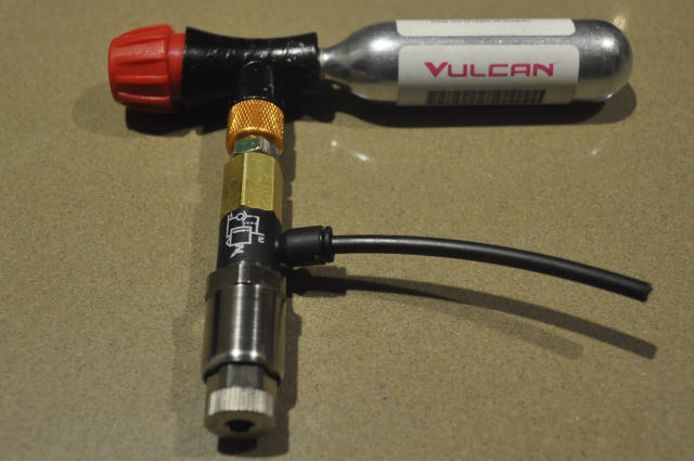
I fitted an M5 to 4mm airpipe fitting to the rear of the torpedo tube with an M5 nut glued to the inside of the tube and enough fittings to test it with an air compressor to see how well it would work. I also tried firing the torpedo with a deodorant can as I have been thinking about for a few years - with very disappointing results! So I went looking for compressed air at high pressure in a small package and came up with the CO2 cartridges used to inflate (or re-inflate) bicycle tyres, these are small and can push 300PSI, hmmmmm! I went back to the air parts supplier and got some right angled connectors for the tubes as the pipe can then disappear back into the forecastle.
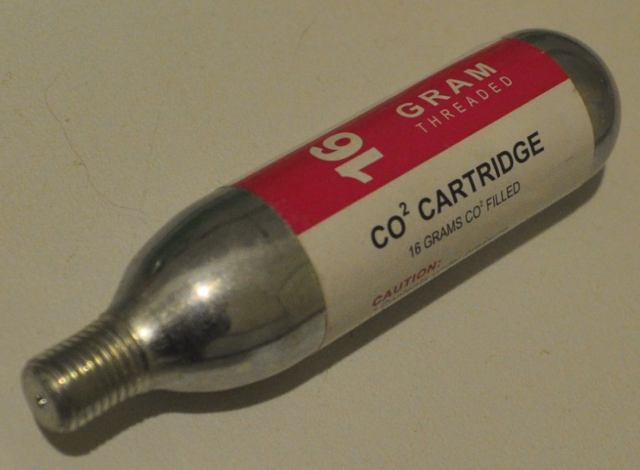
The 16g CO2 cartridge. The thread on these is 1/8" NPT (US National Pipe Thread I believe). The 4mm pipe adapter is 1/8" BSP (British Standard Pipe) so I need an adapter from one to the other. The NPT thread part also needs to pierce the cartridge.
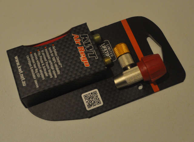
I found a good bicycle shop and spoke to the tech guys to find the best way to connect the CO2 bottle and they suggested this adapter (above) with a valve, so I can screw the bottle on with the valve closed without losing all the CO2. Only problem is I now have a different screw thread to deal with (Schrader). This kit also comes with 2 bottles.
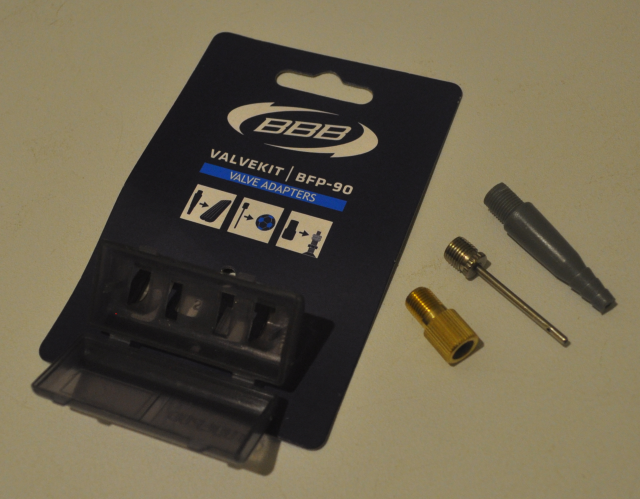
I also bought a bike valve kit for a few dollars which gives me a few different methods of connecting to the Schrader bike valve thread.
See the test firing below, note that I experimented with the one CO2 bottle a few times and launched the torpedo several times before the video was done so one 16 gram cartridge should launch about 4 or 5 torpedo's, not bad for about $3.99!
Watch the video of the (second) test launch.
Watch the video of the Third test launch.
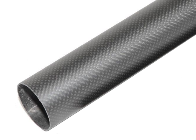
Carbon fibre tube with 1mm wall thickness - this is perfect size for 1/20th scale torpedo tubes and comes in 500mm lengths - this will be in the pricelist soon.
Watch the first video of the carbon fibre torpedo tube test launch.
Watch the video of the 2nd carbon fibre torpedo tube test launch. Just a short burst of air!
My son accuses me of having an evil chuckle at the end, I am just very pleased!
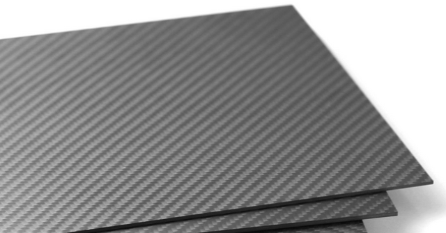
Carbon fibre sheet to make the opening wedge shapes out of. NO - scratch that idea - I cannot cut this on the laser cutter, it just melts and makes a horrible smell! Back to plywood for the infills.
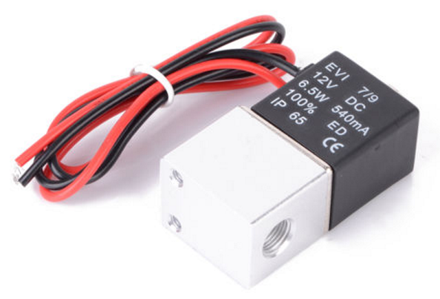
12 Volt electric air valve with 1/8 BSP inlet and outlet for controlling the torpedo launch air pressure. So far I have purchased 4 different versions of these solenoids and they all fail to operate, even on 24Volts, doing some research tells me that the output pressure from the CO2 bicycle tyre cartridges is around 700 PSI, way too much for the solenoids which are only rated to around 140 PSI (10 Bar). I recently received a small pressure regulator and this allows the solenoids to work when the pressure is reduced, so watch this space! We'll have a working Bofors canon as well soon, firing 2mm BB's.
The torpedo tube door and door surround
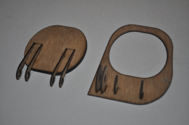
glue the hinge end supports onto the door and the door surround.
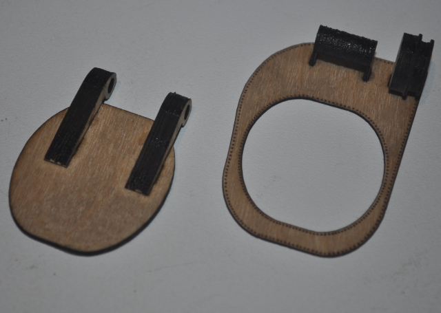
Step 2 infill the hinges.
Hinge put together with a piece of 4mm stainless rod.
Door opens.
Door closed over carbon fibre torpedo tube.
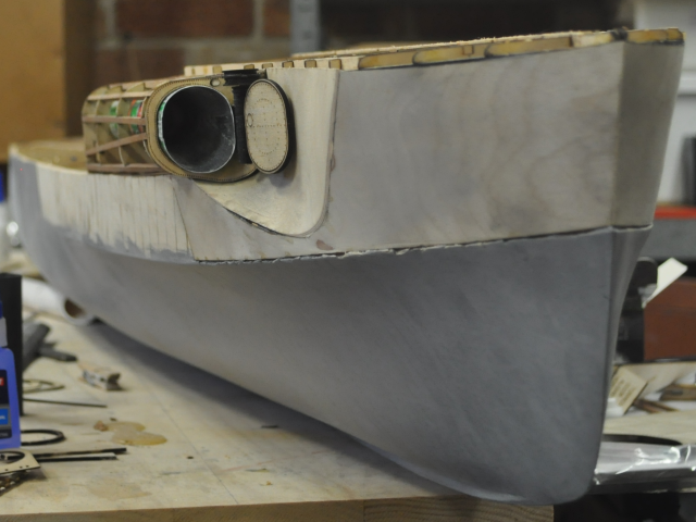
Door open and a good view of the new carbon fibre torpedo tube. This has taken me weeks to get right but it really is looking very good now.
I spent quite some time trying to work out how to launch the torpedo and before doing that how to open the torpedo door, the original boat used a long rotating rod back to the torpedoman and as you can see on the photo above there is a worm drive above the door hinge and the rod disappears back into the angled panel. I tried all sorts of ideas and after about revision 20 I ended up using the section between the top door hinge and the bottom of the worm drive gear box, I put a couple of holes on either side and I will run a wire or elastic material around a pulley and into the forecastle where I have already made allowance for two servo's (three actually but one position doesn't work because the centre spar is in the way ( this was to operate the forward canon)). At one stage I figured I could just launch the torpedo and let it open the door but alas it just blew the door right off it's hinges!
This is the new revision, here I am making up the door hinges, it all needs to line up nicely or it won't operate smoothly so it's important to get all the pieces nice and square, the top and bottom pieces of the door hinges are slightly different to the infills so I have glued them on first and lined the whole thing up with some 4mm stainless steel rod.
This is the revised angled panel and main hinge and worm drive gearbox housing, I changed the hinge supports to make them much stronger and also angled them at 45 degrees so that they cannot be seen from the front, there are also some cutouts to clear the door when it is closed, I also angled the worm drive gearbox housing mounts at the last revision but I changed it back to the way it was, as the 45 degree mounts were way too visible, now you can hardly see them from above. in the photo you can see the two holes for the pulley drive belt just below the worm drive gearbox housing. The other oval hole is for the worm drive shaft to disappear into, this will be a piece of brass tube probably.
The two door hinge outer pieces in place, these four pieces fit in slots in the door outer panel.
The door hinge middle pieces are in place and the door operates smoothly. The pulley is not in place yet, the pulley gets glued to the door hinge so as it turns it opens the door, there will be another similar sized pulley on each of the servo's.
You can see the pulley in this shot, it is made of three circles of 0.8mm material with the top and bottom pieces slightly larger in diameter so a wire or similar will stay put in the centre.
This is the blank angled panel before the hinges are glued on.
This shows just the two main hinges in place, these are made from 5 layers of 0.8mm material. The section between these two hinges will be filled in with about 10 circles of 0.8mm material making sure to use only enough pieces not to push the hinges apart.

This picture shows the entire hinge and the pulley in place, the worm drive gearbox goes on last as it can then be adjusted slightly to make sure the whole thing doesn't bind.
The completed door and panel assembly. It needs to operate really smoothly. I will make some shorter shafts once it is all fitted on the boat and glue them in place at the worm drive gearbox at the top.
The torpedo door is made up of three 0.8mm layers glued together.
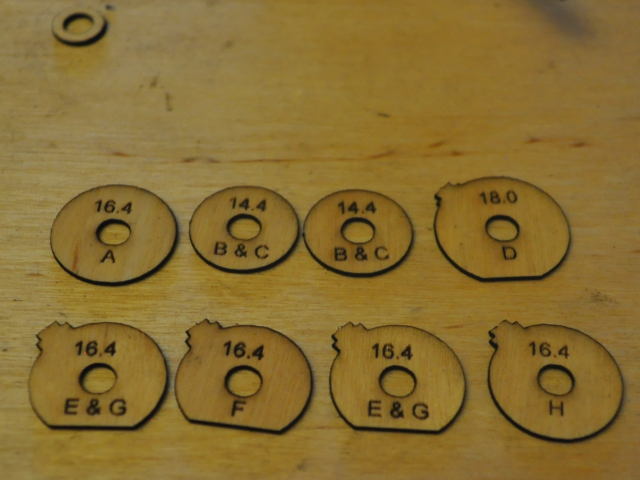
This photo shows the pieces of the worm drive gear box housing, because they are a little complicated I have labelled them A - H in top down order, a couple of pieces are the same.The flat parts cut off at the bottom form a valley where the drive shaft will join them.
Starting to look like an SBoot now, door open.
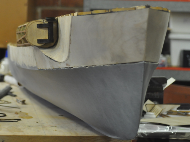
Door closed.
Both doors closed.
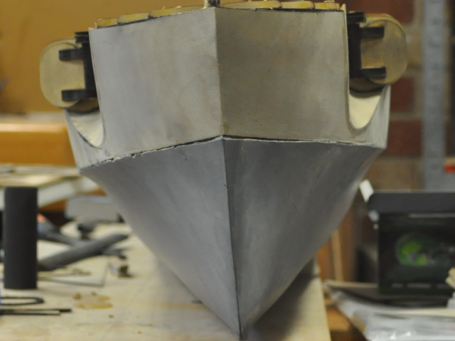
Another bow view.
Top view showing servo mount fitted and both torpedo doors.
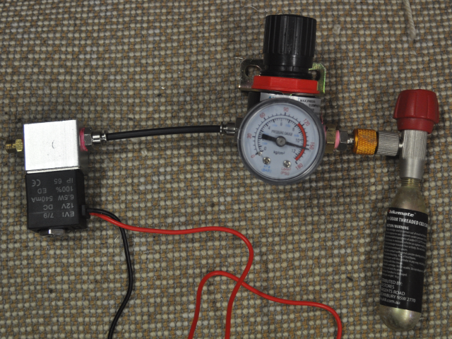
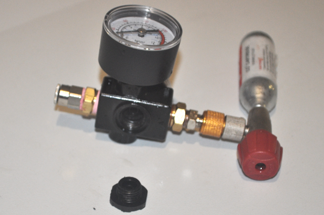
This picture shows a working launch system, albeit getting a bit complex. The regulator is shown set at 150 PSI which is the maximum pressure that the solenoid can switch.
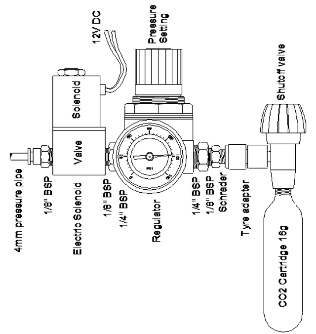
A drawing I did of the working CO2 launch setup, as I need to see where this is going to fit and it also describes the various adapters needed to get from the CO2 cartridge to a regulated and electrically controlled air output to feed into the launch tube(s). If I put a small manifold after the regulator I can add as many solenoids as I like to control the torpedo launches separately and also maybe activate the 40mm Bofors canon firing 2mm ball bearings. This will also need a control board to switch the solenoids for a particular time period.
The most likely place for this setup is in the Kallotte Bridge as the CO2 cartridge will need to be changed regularly.
I have managed to find a small regulator that can replace the huge one above.
This regulator is from a French company "Parker Legris" and is available with different size pipe outlets, the one shown has a 4mm outlet and all have a 1/8" BSP inlet but I bought some 6mm to 4 x 4mm outlets manifold so that I can add a number of electric solenoids to perform different functions so I may need to get a different one. This regulator seems to freeze as the CO2 cartridge gets really cold and covered in frost when you let the gas out, maybe I need a bit of time between attaching the cartridge and launching, should be OK in the boat.
The Parker Legris part number for the unit above is 7300-04-10, see www.parkerlegris.com
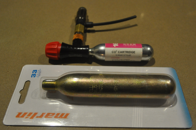
I also found a larger version of the CO2 cartridge with 33grams of CO2, however I haven't found a suitable connector for it yet, the thread is 1/4" BSP but would need to have a hollow needle type probe to pierce the container.
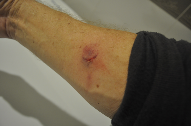
OK, the CO2 cartridges have more than 300 PSI pressure, hence the pressure regulator to bring that down to around 100 -120 PSI so that the electric solenoids can operate, however the large pressure regulator has a plastic screw in cap, on the bottom, which houses the regulator valve and a compression spring. I had some leaks in the connectors and sealed them with a Loctite pneumatic thread sealer and then submerged them in some water to see if there was still any leaks, when all of a sudden the bottom cap blew off with a loud bang and hit me in the arm leaving the damage shown above, So be careful people, this is serious stuff and not to be messed with. I shall try to find a non Chinese pressure regulator that is built a bit better than this one!
I have the small French pressure regulator but it is physically small and it freezes up with the expanding CO2. Also from a safety perspective I initially connected the French regulator to the CO2 cartidge using plastic pressure pipe and when I turned on the CO2 cartridge valve there was about a 1millisecond period where I watched the tube expand like a balloon and it went BANG. I saw it happening but was powerless to react fast enough. It made me go deaf for a few minutes.
So what I am saying is this stuff can be dangerous and also we don't want to blow a hole in the boat hull and suffer a sinking either!
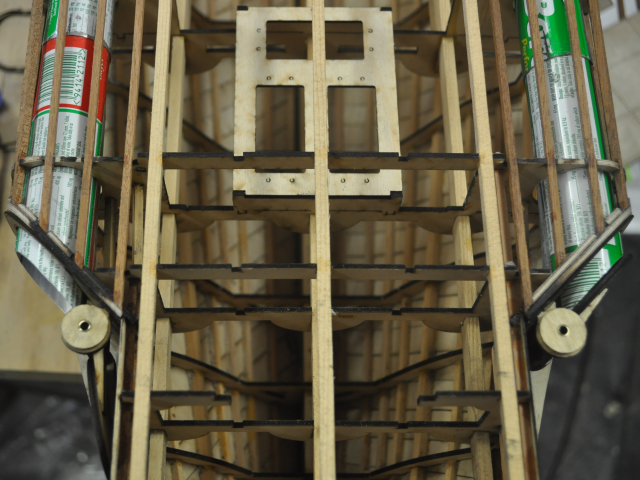
There are two torpedo storage racks on each side of the aft deck, a shorter one just behind the torpedo tubes and a longer one further aft.
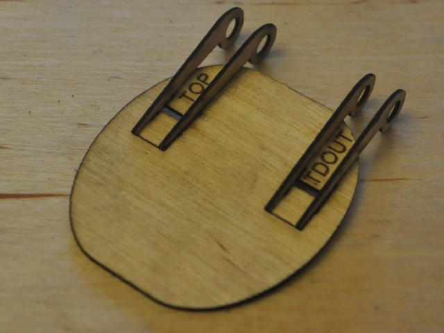
These are the major parts of the shorter rack rails, the vertical rail sections have tags that fit through the two layers of horizontal rails and line them up together.
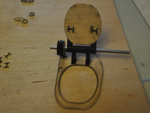
This photo shows the two rail assemblies (a left and a right version) made up and one of the feet made up.Note that the middle foot is smaller than the end ones. There is another small dog leg section that fits below the bottom horizontal rail.
Historical photo's
The pistol or exploder assembly.

Another view showing the impeller, which acted as a safety mechanism, so that the torpedo would need to move through the water to drive the impeller and thereby unlock the whiskers.