The Deck
(for the German S-100 Class Schnellboot (Fast Boat))
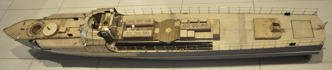
There are two decks on this beast, one at the front (the foredeck) and this one, a much larger deck at the rear ( the aftdeck), I decided that they should both look planked as I have one photo that shows it planked, however this photo is of a boat that was almost certainly re-fitted after the war as many of these boats were.
The aft deck has two layers, a sub layer on which I have marked all the fitting details and the top etch planked layer which I haven't marked except for the planking because you may not want to fit it out as the same boat as me.

Once the deck is on we can fit it out with ladders up to the Kallotte, torpedo racks and hand rails.

My final torpedo racks fitted.

The evolution of the torpedo racks, I started off quite low to the deck (lower), then raised them up a bit and then decided from researching all my photo's that the torpedo has to be in line with the torpedo tube (upper) so that in real life the crew just needed to push them into the torpedo tube, they did not have a crane to lift them up.

The hand rail starts from the forward end. Note that the ladder is (and was) in the way of loading the torpedo, the original ladder was removable, I won't be loading torpedo's from the rear of the tube so my ladders are glued in place to the deck and the side under the kallotte but not glued to the kallotte as it is removable.

The forward section of the rear port side railing, rear torpedo rack and a brass bollard. The railings are made up of commercially available posts (from Floataboat in Melbourne) and 1mm brass rod. There are a couple of angled "stays" on the two left posts which are the same posts screwed into the deck then cut off, bent over to touch the upright posts and then a dab of superglue where they meet.

This shows the construction of the torpedo rack.
Another view.


The torpedo has to be able to slide into the torpedo tube without any lifting involved.
The sub deck in place.
Another view of the sub deck.
The forward end of the sub deck.


The beginning of the starboard aft railing, the posts are screwed into drilled holes in the deck.

There is a post screwed into the rear section of the forward superstructure to hold the life raft, I have cut the top "ball" off and drilled a hole in the life raft to hold it in place.

The life raft glued in place.

These are the posts, you need nearly 50 of them!

This is a picture showing the dimension in the other language! When is the US going to get with the program and go metric?
The finished Railing.

The stern railing detail showing the three legged corner posts and the three legged stern centre post, note the hooks on the ends of the rails and the centre post, these allow for chains or ropes that were able to be removed to launch depth charges or deploy mines over the stern. I made these hooks by bending the 1mm brass rods around a small pair of needle nosed pliers before putting the rods in place.

The stern post finished, again the two extra legs are full sized posts that have been screwed in, cut off and bent over and glued to the main post.

The port aft corner post with hooks.

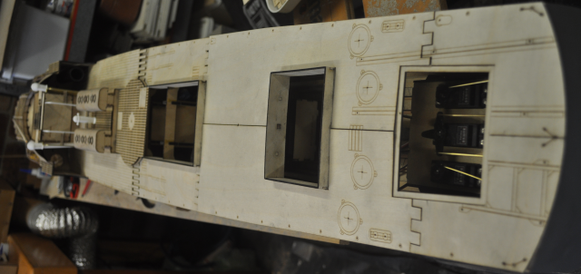
The aft deck temporarily in place with the mid superstructure in place. I have allowed small holes for the stancions along the sides.

There are a couple of joins in this deck as it is very long, the sub deck joins and top deck joins are in different places.

Before we can fit the deck we need to file down the top edge of the planking where it will meet the deck.

Using a fairly rough "bastard" file, file the tops of the planks level with the deck edge timber.

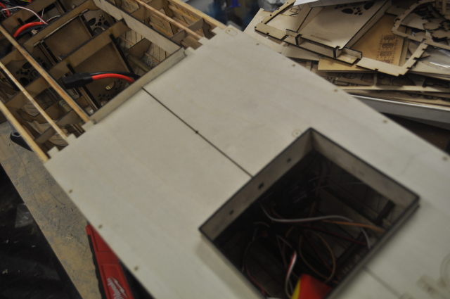
This shows the stern sub deck in place, there is a removable hatch above the steering gear that was also on the original WW2 boats. I have made a two layer sub frame under this part of the deck to make a well for the removable hatch to fit snugly into and to join the rear sub deck to the sections in front of it. I originally cut the rear sub deck into two halves but it can be in one piece.

This shows the subframe from below (as well as the joiner to glue the two halves together).


This photo shows the stern deck hatch fitted into the sub deck frame which obviously goes under the decking. This hatch is great as it gives us access to the steering gear but it shouldn't need to come off very often if at all.


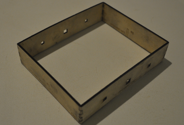
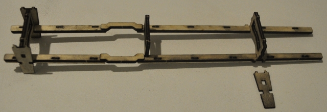
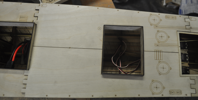
To stop water entering the hull in operation the holes or hatches through the deck need to have upstands around the openings, the upstands also serve to hold the removable superstructure sections in place and also align the various ribs in the correct place so that things fit. The photo above shows the aft upstand, notice that it has holes in the forward and aft ends, these allow the deck support beams to be accurately and securely placed. This upstand floats between ribs so that it can be placed correctly to fit the sub deck and deck.
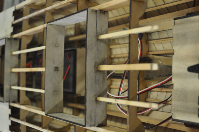
You can see from this shot that the same holes exist in the aft end of the forward upstand so that the deck beams can connect the forward and aft upstands via ribs 4 and 5. Behind the aft upstand there are short deck beams that are shaved down on the top to fit under the aft hatch support.
This photo shows the same deck beams from forwards looking aft.
This shows the sub deck pieces fitted loosley in place and fitting around the upstands.
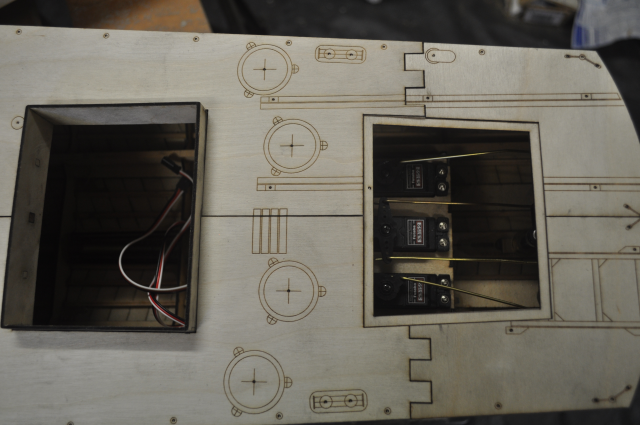
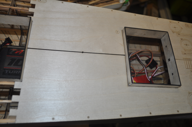
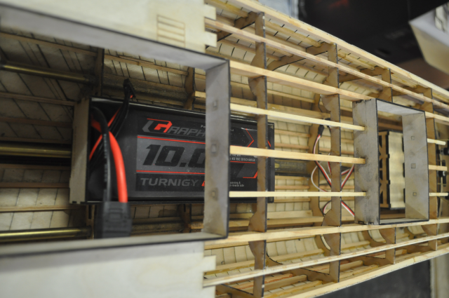
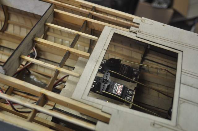
Here you can see the access through the aft hatch to the steering servo's and rudder tiller arms.
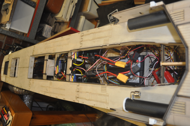
A view of the complete rear sub deck, upstands and aft hatch support.
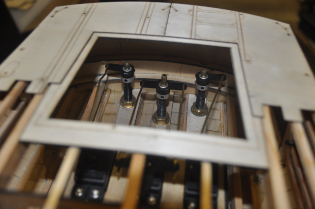
Another view showing the three rudder tiller arms with grub screws facing forwards so that they can be removed later if necessary.
This view shows how the deck beams fit under the edge of the aft hatch support surround.
The sub deck needs to be put in place to get the correct distance between the forward and aft upstands.