Hull 2 - Propshaft 1/20th scale
The Hull-2 motors are mounted closer to the original boat engine location and are much further aft (rearward) than in Hull 1, this means that the prop shafts are much shorter and can be bought as complete 8" types and then modified to suit, rather than having to make up the entire thing yourself, however, they are fairly expensive for what they are.. I have allowed for both 6.35mm (1/4") or 8mm outside diameter stuffing tubes in the Hull-2 1/20th scale kit which you can choose when making up the keels. Moving the motors back also means that the boat can be balanced better as the batteries are further forward in front of the motors.
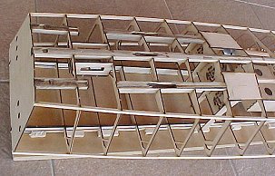
This is the 1/20th Skeleton kit showing the prop and rudder keels
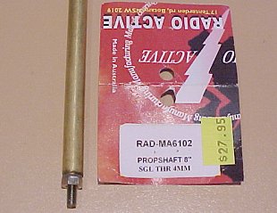
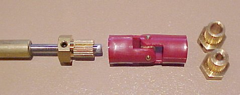
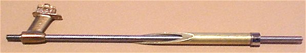
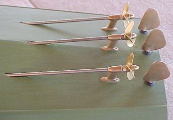
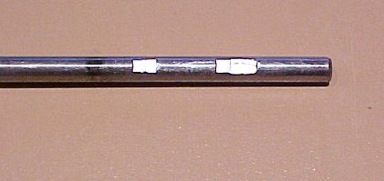
This is the 8" propshaft and the universal couplings that used in the 1/20th scale Hull-2, the brass parts of the couplings are available in every metric and imperial size you might need to suit any motor or propshaft size, shown here are 4.0mm, 5.0mm and 3.18mm (1/8") I believe these are available all over the world and are branded as "Radio Active" in the UK and Australia.
The brass outer tube (the stuffing tube) on the propshaft is 8.0mm O.D. and 5.5mm I.D. The soft metal (bronze?) bearings are split and spring open slightly so they are larger than 5.5mm when out of the tube. There are a number of Nylon, Iglidur and other high temperature plastic types of pre-made bearings in 5.5mm O.D. 4.0mm I.D. which are possibly worth trying also but I had difficulty finding a good match between available brass tubing and bearing sizes. Any input on this would be appreciated!
Prop shafts, silicon bronze cast struts and cast rudders fitted, there will be three more struts further up the shafts, fitted later. I cut the prop shaft stuffing tubes down to 110mm (4.33") long, drove out the bearing from the short left over end using the squared off blunt end of a drill bit that just fitted the inside of the tube and then pressed it into the new shorter tube. I was going to mount them with the propshaft tube ends sticking out of the boat with slightly rounded square cut ends and then not fit the extra forward struts but then I decided that that would look crap, so I then pushed the bearings further up the tubes and cut the tubes at an angle to match the hull openings so that the brass tube would finish flush with the hull, much easier to do than I thought it would be actually. I then fitted the struts and tubes as a set, one at a time, using lashings of Araldite and inserted a long piece of 4mm diameter stainless steel piano wire (which is used a lot for propshafts) to line up the strut, shaft tube and right up through the motor mount to keep it all in line while the glue cured. The universal joints just happens to be the same size as the motor mount hole so you can slip it over the long 4mm shaft to set it at the center.
The middle strut needed a little "fitting" into the hull at the front as its angle with respect to the hull is very slightly different to the outside struts.
Put a thin smear of grease on the piano wire and make sure you don't epoxy it in!!!
You may also notice on the photo above that I have three different propellers fitted, two different shape 35mm types and a 40mm types, all Raboesch, I have fitted them with a locknut as they are all left hand propellers but once I have decided on the final type to use I will use an anaerobic glue or locktite to lock them on to the shafts and get rid of the nut as it just doesn't look right.
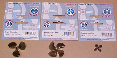
I have bought some new 40mm props, two more of the Left Hand 156-06 which is the closest shape and type to the original boat, one of a 4 bladed type which Raboesch recommend for faster boats which is a RH type as I want to try having the center prop rotating in the opposite direction to the outside props and I also found a cute little 4 bladed 20mm prop for the 1/35th Hull-2 model which has an M3 thread which may be a bit big but finding any sort of 20mm prop is tricky, there is also a 3 bladed version at 20mm but the blade area looked a bit tiny so I will try three of these first! These would be good on a torpedo as well!
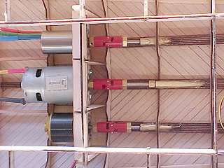
The inside ends of the propshafts showing the three red universal joints between the shafts and motors, I have since added a model airplane 4mm (5/32") wheel collet to each shaft so that they cannot pull the brass spline out of the universal when going backwards.
Note: Just because you have universal joints is no reason to not bother lining up the shafts properly, if you want serious performance the inner propshaft should line up exactly in the middle of the motor mount hole!
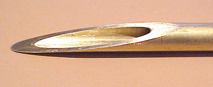
A drawing and photo's of the propshaft, I made mine from the 8" long "Radio Active" ones that I bought (the photo at the top of the page does not show the correct length, it was just a trial). The brass tube MUST come out through the hull planking so the opening can be sealed properly, so you can't really install it before the hull covering goes on. From a filing/sanding and finishing perspective the brass is probably easier to sand than the birch ply, so it could be sanded flush or you can fill the gap if it is slightly below the surface. The center tube needs to be filed to an angle on each side to make the 'V' shape of the keel.
The motor end of the stainless steel shaft needs a couple of "flats" filed into it so that the grub screws in the collets and universals can bite into the hardened shafts securely and still allow the shafts to slide out through the bearings without scoring them.
The motors should also have a flat filed on their shafts for the same reason if they don'r already have one but the motors have magnets in them so wrap the motor in a plastic bag with just the shaft sticking out, or put the shaft through a tight hole in a piece of cardboard, file the flat and then blow away the filings, or use a magnet to get rid of them.
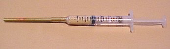
The Grease Gun
Once the hull has a couple of coats of paint and the propshaft stuffing tubes are fully installed it is time to lube them up properly. I have used all sorts of fancy grease in the past and the bearings still wear out fairly quickly, so this time I have used some Valvoline high temperature grease and I made up the "grease gun" above by using a 3mL syringe that I bought from the casting supplies place (for mixing epoxy glues) and a piece of my favourite material, brass tube, 4mm OD which fitted perfectly onto the plastic nozzle with a piece of 4mm ID tube over the top, some Araldite to keep it on and voila!
Fit the propellers to the ends of the shafts, if you are happy with the size, use some Locktite or other anaerobic glue, then fill the grease gun with grease by sucking it up out of the container, smear grease lightly over the propshaft and also into the strut holes and push the propshaft through the struts and up the stuffing tube until the motor end is not quite to the top bearing, put the syringe down through the motor hole until the 4mm brass tube is well into the top bearing and squeeze! once the air is gone and the stuffing tube is filled with grease it will start to push the propshaft out and then if you push it back in, it will push the syringe plunger out, once that happens you pretty much know the tube is full of grease, do that a couple of times and you can remove the grease gun and push the propshaft all the way home and put the locking collet on.
Fit a motor and spin fast!!
© Copyright 2004 - 2024 - John Drain