40mm Bofors Cannon
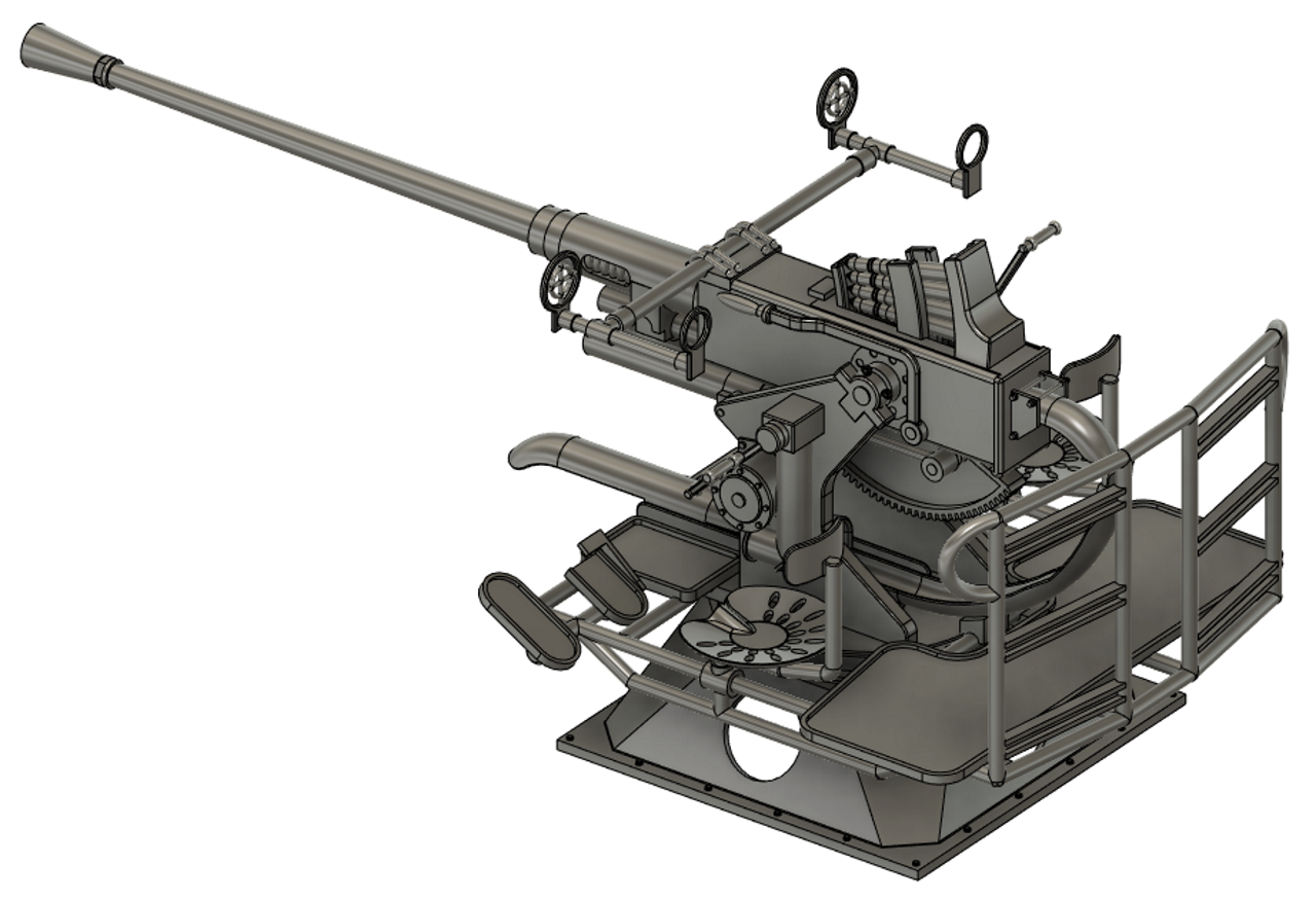
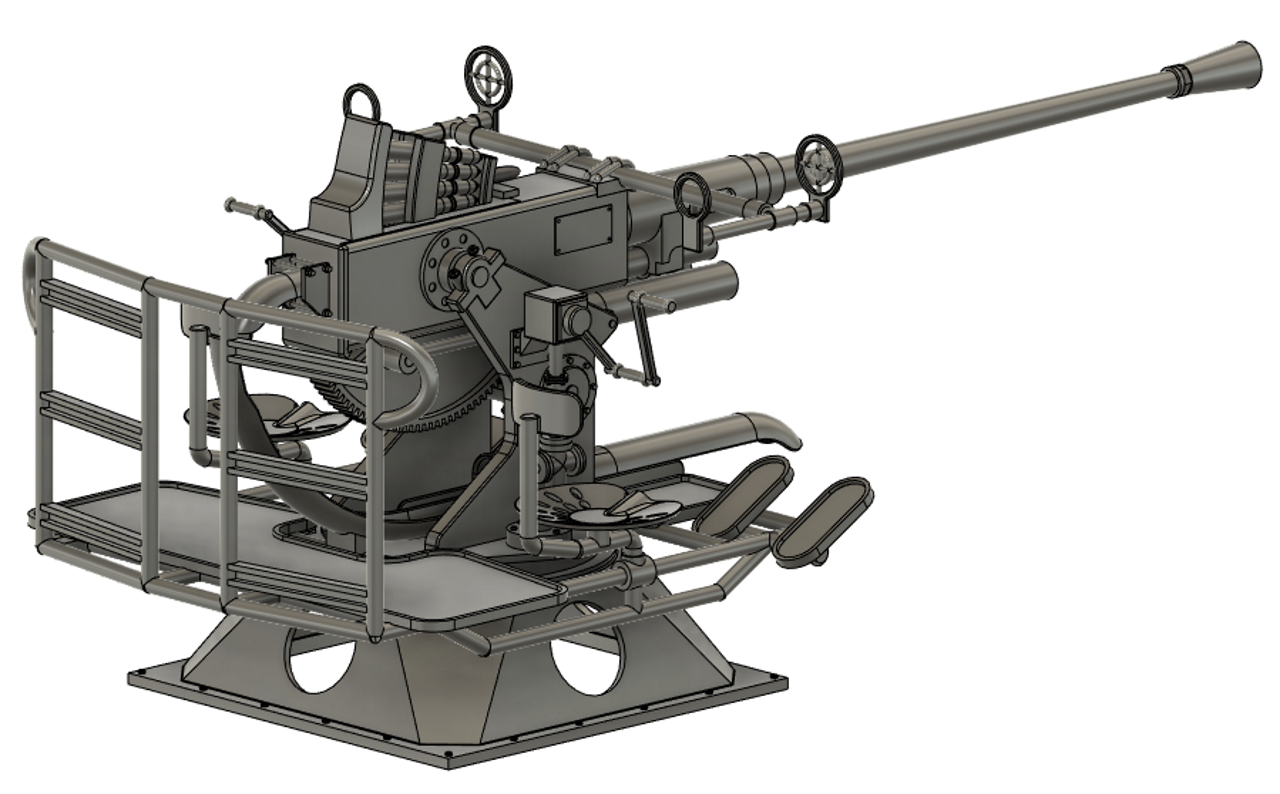
The 3D version of a 20th scale Bofors Canon.
The objective is an operational 1/20th scale 40mm Bofors Canon.
2016
Since I started this project some 21 years ago when there was almost no information available - or it was very hard to find - there are now many drawings, 3D models and photo's available. I will pursue the 1/20th scale armaments, as there is very little available, but for the 1/35th models of the Elco PT Boat and the Schnellboot I have purchased available kits and made them up. I personally find the 35th scale too small and fiddly, as I am getting past my prime I suppose, I have no idea how people make up 1/72 or 1/350th scale models!
There are some fabulous designs available on Shapeways - www.shapeways.com
A very good World of Warships, Naval Weapons, Bofors Documentary on Youtube: https://www.youtube.com/watch?v=TqM1PS1YTo0
Or this Forgotten Weapons.com Documentary: https://www.youtube.com/watch?v=7dJDn5F1GQk
Below is a kit I made up from a "Hobby Boss" kit, this was actually a GMC truck with a Bofors mounted on the rear tray, I only wanted the Bofors so I have gifted the rest of the truck to my son in law to make up if he wants to. This kit is awesome, very well detailed and very well documented and comes with etched brass fine detail parts. I would highly recommend this model.
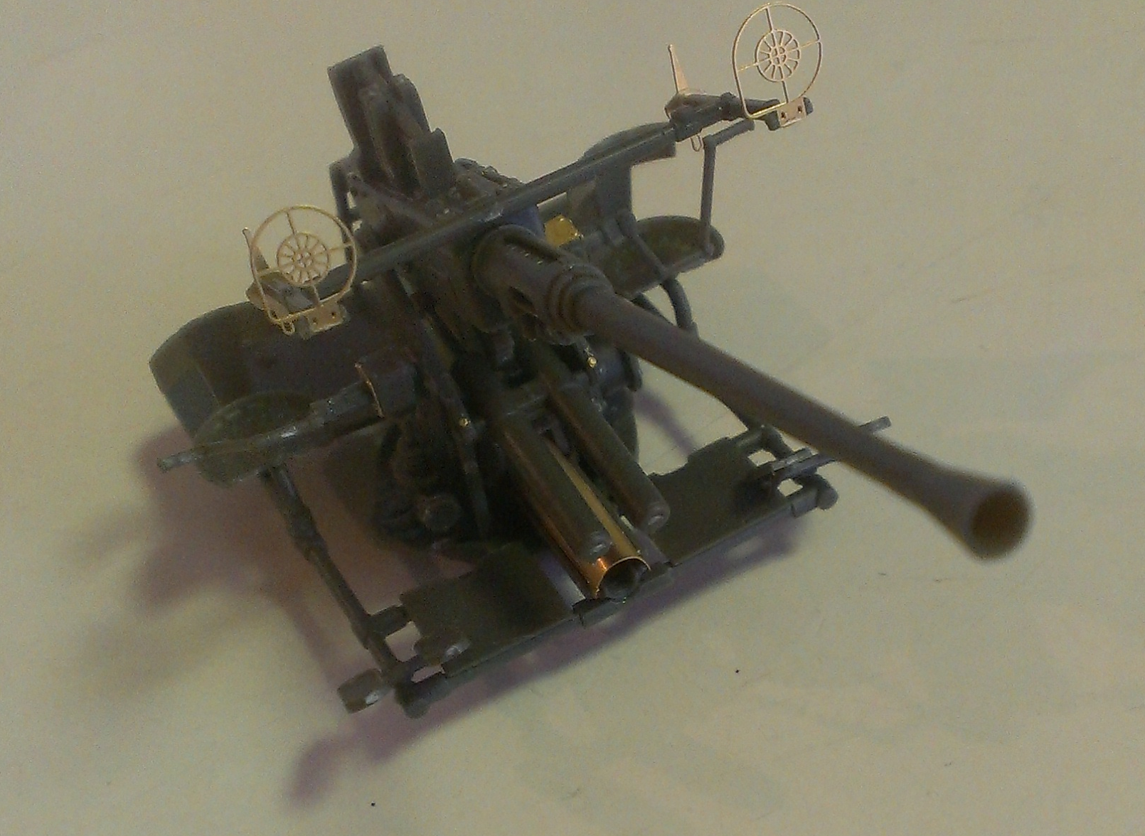
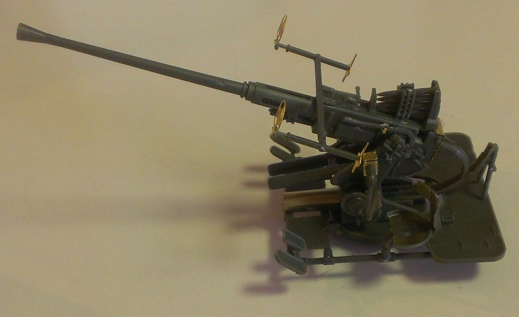
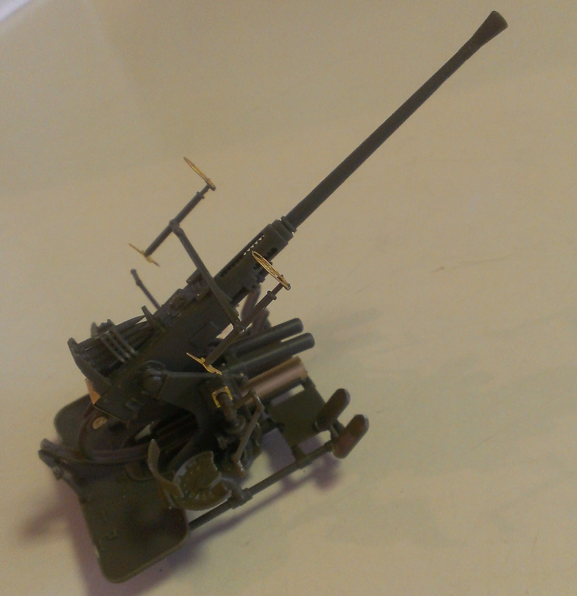
I need to add the rear railings to use this on the Elco but it would be fine as it is and painted light grey to use on the Schnellboot.
2006
The plan is to use spark ignited propane gas to propell 2mm ball bearings or for the feint hearted leave the ball bearings out and just have flames coming from the nozzle.
My thanks to a friends dad who found a copy of a 1959 British Model Maker magazine with an article and a fabulously detailed drawing by a Norman A Ough of the 40mm Bofors used on British subs and destroyers. Some modifications are required to this setup, as it appears that for PT boat use, a lot of the heavy mount and magazine have been ditched probably for weight reasons and it looks as though most of the hydraulics may have been thrown overboard as well. However our thanks to Mr Ough, wherever he may be, for the great detail.
The drawing above is based on the 1959 drawing and has yet to be converted (or finished) to suit the PT-Boat.
We do have a Paslode gas nailgun propane fuel cell and metering valve to play with!
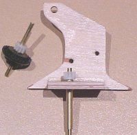
 The elevating mechanism
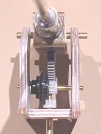
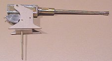
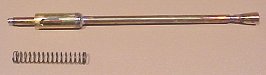 The Barrel
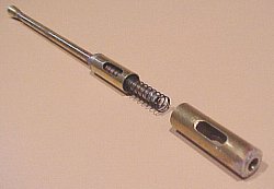 Recoil mechanism
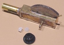
 The elevating drive gears are modified Scalextrix gears
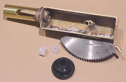
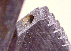 The main elevating gear showing hole drilled for 2mm brass training stop. This
stop prevents the drive gear falling off the end of the main elevating gear.
The main elevating gear showing hole drilled for 2mm brass training stop. This
stop prevents the drive gear falling off the end of the main elevating gear.
 Make sure the main elevating gear is precisely located, straight and
perpendicular or it won't work properly. I used the remaining 2/3 portion of the
gear to precisely locate the centre hole.
Make sure the main elevating gear is precisely located, straight and
perpendicular or it won't work properly. I used the remaining 2/3 portion of the
gear to precisely locate the centre hole.
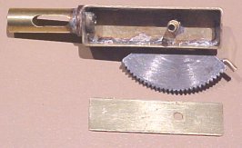
 This shows the elevating training stop.
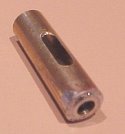
 The gas chamber
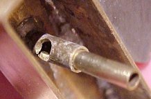 The gas entry hole
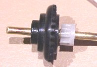
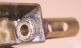 The nozzle bearing
 Side plate and base showing the elevating drive shaft and bearing and the pinion gear, again a Scalextrix pinion gear.
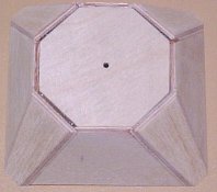 The Elco PT Bofors base
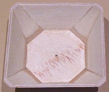 The Elco PT base
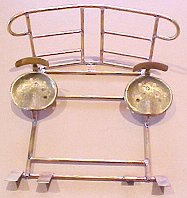
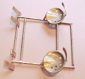 The gun operators
carriage and seats
The gun operators
carriage and seats 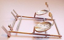
The basic carriage is made from soldered brass tube, rod and flat strip from the hobby shop. The seats were made by carving and sculpting the bottom shape into the top of a piece of a broom handle held in a vice and then tapping and peening the thin brass sheet into the shape of the "mould". I made several moulds before coming up with the seats shown above, too big, too small, wrong shape etc!
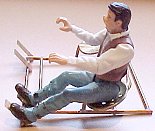
A heavily modified (not finished) Jurassic Park figure in the gun operators position. surgery has been performed on his legs and arms to shorten, bend and straighten him into the right position to operate the elevating handles. He had some sort of cowboy looking boots on so I carved them off, a helmet and a bit of kahki green paint and he will look the part.
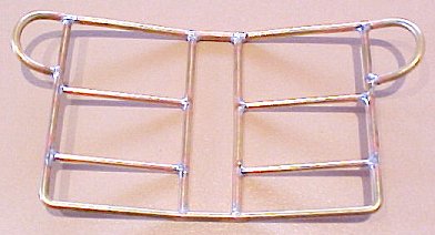
The Back Rails made from Brass rod, I soldered it all together while it was flat and then bent to shape (very easy).
There is a piece of flat strip (difficult to see) holding the Back Rails to the carriage in the middle (underneath)
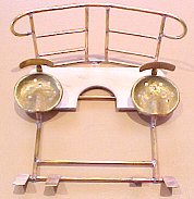
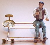
The finished carriage with the rear deck attached. From pictures that I have, I'm not sure, but the two top rungs of the back rails looks like they may have wide rungs or almost shelves on them, this makes some sense as the back rail assembly on the later boats was as shown, a solid fence (ladder), making it difficult for the gun loader to get to the ammo closet, so I am thinking that there was maybe a loader standing on the rear deck behind the cannon and another guy at the ammo closet passing him clips of 4 shells which he would need to put somewhere?
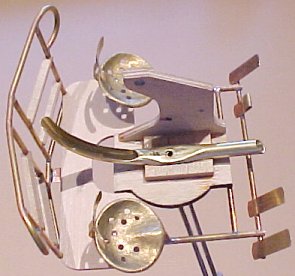
I have added some strips of 0.8mm (1/32") ply to the back rails and I have also added the spent cartridge chute, I made this from brass tube, which I bent to shape first using a tight fitting long spring around the outside to stop it collapsing, and then filed to shape, make sure the radius is correct as the rear bits of the gun must travel in the slot. I had to cut away the bottom and flatten the top where the hole is to allow for the elevating gear which is attached to a spindle that goes down the hole.