The Propeller
The modelling objective here is to make (or buy) an accurate 1/20th scale Propeller that looks and performs like the original propeller which was 28" diameter and 28" Pitch.
My drawing of the complete propeller with locknut, and rotated to be the correct overall height (diameter) above the propshaft on the upper blade to make sure it clears the hull...
My drawing of the propeller copied from the historical drawing (below).
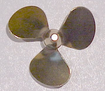
I bought some new propellers at a local model shop - 35mm Dia Brass propeller
Made by Raboesch Hobby Products - Netherlands - part/no: 156-04 (35-L-3bl-M4) (left hand)
The Propeller Calculations
I did some calculations which I think prove that my current model propellers are far too big and I have recently purchased 3 new 35mm props for the model (should be 35.56mm for 1/20th scale) these look quite good but are as yet untested. I am always looking for better speed, lower motor temperatures and longer battery duration.
A propeller has a pitch, usually measured in inches, which is designed to produce a smooth spiral flow of the blades through the water which if it could be perfect, 100% efficient and unaffected by water turbulence, air bubbles, the drag of the hull, spoilage by the propshaft and skegs etc. would move the propeller that distance (the pitch) through the water for each revolution of the propshaft. The mathematics of propellers is quite complex and quite frankly we don't know the efficiency of any particular model propeller and it could be anywhere between 40 and 75%, also the blade shape is very important to working out the true median or mean blade diameter. I am in the same position as most modellers of trying to fly in the dark so I devised a much simplified method that seems to work reasonably well, at least a good starting point anyway!
Take the newly purchased model propellers at 35mm overall diameter with an 8mm diameter hub, the average blade diameter (the mean blade diameter is where most of the push comes from but varies with blade shape so we will use the average blade diameter for simplicity) is at a point on the blades at 21.5mm diameter (halfway between 8 and 35) which would travel a circular distance of 67.55 mm per revolution (21.5 * Pi) and if we assume a 1-1 geometric pitch (I don't have a pitchometer so I can't tell exactly) the linear distance travelled would be theoretically the same 67.55 mm at 100% propeller efficiency or say 34 mm per revolution at 50% propeller efficiency (50% slip). Therefore at 3000 RPM and a 50% efficient propeller the boat should move 3000 * 34 mm or 102 metres in 1 minute.
Our scale speed needs to be 1/20th of 41 Knots or 2.05 Knots or 63 metres per minute (or say 200 feet per minute), at 3000 RPM the prop should travel a linear distance of 0.021 metres (or 21mm) per revolution, this would be true of a 30% efficient prop. Close enough!
So if we had a gearbox on the driving motors with a fairly typical 2.5 to 1 gear ratio this would need a motor speed of somewhere between 4600 and 7500 RPM to achieve our scale speed. A typical Mabuchi 540 motor (model 5045 4.5 -9.6Volt) http://www.mabuchi-motor.co.jp is most efficient at 9660 RPM so we may want to consider a slightly smaller prop or a gear ratio of 3 to 1 or even 4 to 1 or get a scale propeller with a smaller pitch.
As you can see from this drawing of the original PT Boat propeller the average blade diameter is not where the mean blade area occurs due to the blade shape. The mean area diameter occurs where the blade has exactly half of it's "push" area of the blade outside and half inside the mean diameter line and from my measurements this occurs at approximately 18.18" diameter (on the projected view).
HISTORICAL Drawings
Photo's of a full size PT103 class propeller drawing - purchased from the PT Boat Museum - http://www.ptboats.org
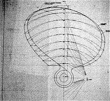
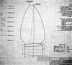
These photo's only show the relevant parts of the original drawing. (only one of the three blades is shown). The two blade shape lines are the views from directly behind and in line with the propshaft (the projected view) and the larger view from the blade's pitch angle (the true length because of the angle of the blade).
There is a patent notice in the bottom right hand corner - US patent #2011821, August 20th 1935 - TFW Meyer.
I wonder if making a 1/20th scale model infringes a patent, probably expired by now though!
The propeller was 28" diameter and 28" pitch and turned clockwise when looking from aft, it had a tapered fit and a keyway onto a 2" diameter propshaft.
SPECIFICATIONS
Dia: 28", Pitch: 28", Developed area: 420.6 square inches, MWR (Mean Width Ratio): 0.42, BTF (Blade Thickness Fraction): Variable (.061), Pitch Ratio: 1.0, Weight of Prop and Hub: 61 LBS, WR� (inertia in air) LB. IN�: 2754.76

The "Equi-Poise" propellers were made by Federal Mogul Marine of Detroit, Michigan, USA..
Some definitions I found
Technical specifications for specialty propellers include the mean width ratio (MWR). This is found by dividing the average width of the blade, in inches, by the diameter of the wheel, in inches. Typical measurements would be between 0.1 for a knife-like racing prop to about 0.5 for an extremely wide blade for a slow moving commercial barge.
- The original PT103 style prop MWR was 0.42 - some barge!
The blade thickness factor (BTF) is also a decimal number and is always much smaller in value than the MWR. The blade thickness factor represents the thickness of the blade. The average blade thickness is measured in inches, and is divided by the prop diameter, also in inches. The BTFs may vary between 0.035 to 0.048. Thinner blades may be made of stainless steel. Bronze is used for medium blades while aluminum is
used for thicker blades. The leading and trailing edges of propellers affect their performance.
- The original PT103 style prop BTF was 0.061
The tip speed is the linear distance the tip of the blade travels in one minute. First find the circumference of the blade and multiply the circumference by the rpm of the motor. This number is divided by 12 to obtain the feet per minute. Tip speeds can range from 8,000 to 16,000 feet per minute. Excessive tip speed becomes a factor which limits the speed at which props can be driven. Slippage, resulting drag, and cavitation are results of not matching all of the above specifications to the correct hull design. Cavitation occurs when the suction side or back side of a propeller loses contact with the water and spins in a region of vapor or air. This increases the rpm of the motor and slows the boat. Prop diameter, number of blades, rpm, and pitch all have to be considered when choosing a propeller for a particular hull. Propeller design can be studied in a test tank with a clear side for viewing. The tank has to be long enough so that the resulting prop wash does not return to the boat being tested. Final testing must be done with the boat moving at full speed through the water.
- The original PT103 prop tip speed would be 16,000 feet per minute at around 2200 rpm!
One question I have - PT boats were sent to the Alleutian Islands - very cold - and they didn't perform well in the cold water, Why? cavitation maybe?