Brushless AC Motors and Controllers
I have added a couple of video files of Hull-2's performance (Nov 26th 2005) with three 12 cell batteries.

Video003.3gp
or
Video003.avi
or
Video003.mpg
Video005.3gp
or Video005.avi
or Video005.mpg
My thanks to Frank Raisin at Lilydale Lake for taking these with my cellphone (*.3gp files are old cellphone format)
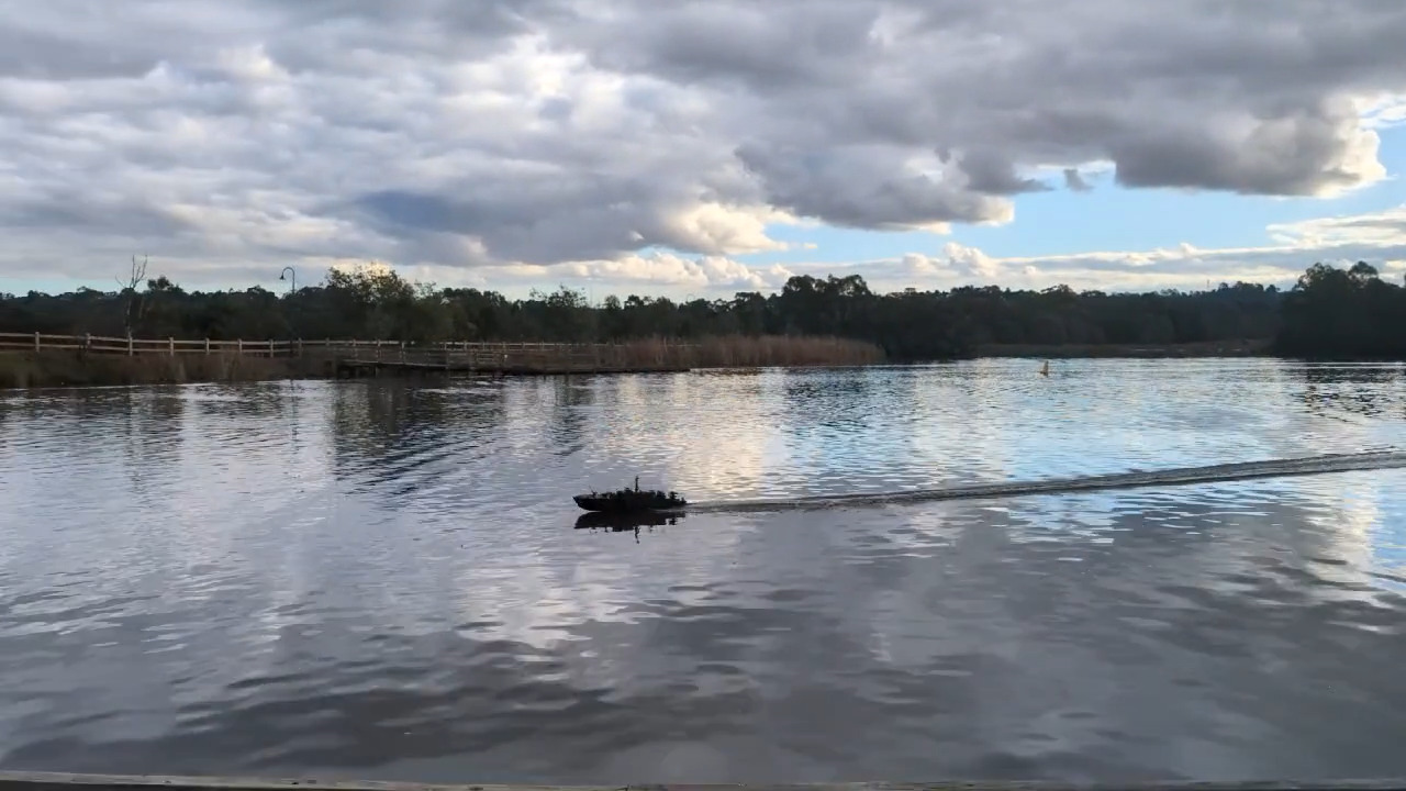
Here is a video from nearly 20 years later, of the same Hull and again at Lilydale Lake (June 12th 2025).
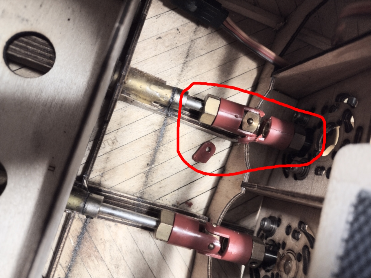
The video above shows an incident near the end where one of the universal joints broke, it seems that broken universals are a sign that one has "enough" horsepower! These universals are 20 years old so maybe their condition is not as good as it was or maybe they are not up to the task? I shall replace them with the metal type [with rubber inner] that I have in the Higgins boat.
(and performance measurements)
The advances made in electric motors, magnets, batteries and speed controller technologies in the past few years is staggering. I can remember when my Kyosho electric airplane was considered a joke by all the serious model flyers, well it was a bit of a brick, weighed a ton and didn't fly very well, weighed so much it broke the wing! Well what a turn around there has been in recent years with petrol engines in model airplanes all but thrown away now in favor of very powerful brushless DC motors and also I do believe that electric powered model boats currently hold the water speed records. Batteries have now got to the stage of being able to supply up to 200 Amps for brief periods.
I want Hull-2 to be extremely fast and yet as scale as possible. Brushless motors are definitely the way to go, they can put out an enormous amount of power and torque and turn large propellers without a gearbox, however whilst there is a lot of information on the size and pitch of model airplane propellers that a particular motor model is able to turn at a particular speed, there is not a lot (if any) information available with regard to their usage on propellers in boats or on cooling solutions without a huge amount of air rushing past..
Most currently available brushless controllers have dynamic braking and no reverse, as airplanes don't need it, dynamic braking is used to fold up a propeller in a glider to reduce drag. The lack of reverse in a boat is a bit of a problem but could maybe overcome with say two brushless motors for forward grunt, without reverse, and one brushed DC motor with a reversible controller. Fast reverse speed is not a desirable feature in a boat as they can get easily swamped. This method would not give us any rudder mixing and low speed maneuverability though except maybe for varying forward speeds on inner and outer motors in a turn, good maneuverability at low speeds needs reverse on the two outside motors! Another issue is that most of the newer speed controllers must be set to minimum/no/full reverse throttle before they will start up for safety reasons and some don't allow re-setting the zero point with some level of forward throttle which poses a problem if we want only one or two of them to have reverse as we may have two stopped motors and one going full reverse, hmmm!
I have a couple of prospective motor and controller contenders and I need to get hull-2 in the water to do some serious testing.
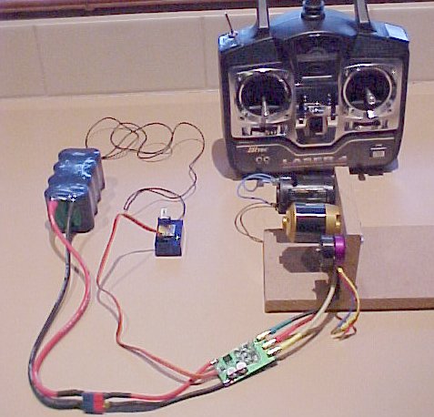
This is the basic setup for a typical R/C brushless controller with BEC (Battery Eliminator Circuit), two heavy wires from the battery pack, Deans socket/plug, normal 3 wire servo lead to/from the receiver and three heavy phase wires to the brushless motor usually with some sort of bullet connectors (several different types available of course). The direction of the motor can be changed by swapping any 2 of the 3 phase wires, and to confuse matters some manufacturers claim this as reversible. We need "fully proportional reverse" without swapping wires!
Note that there are also many older style brushless motors and controllers with three extra small sensor wires, these generally have hall effect magnetic field sensors or optical sensors in the motor to tell the controller the absolute rotational position of the shaft but as the sophistication of the sensorless controllers grows and the cost comes down, these types are losing favour to the simpler and cheaper "sensorless" style motors, where the controllers use a zero crossing of the electrical signal from the un-driven coil to tell the rotor position (only two of the three sets of coils are driven by the controller at any one time). However as brushless and sensorless motors require some rotation to be able to tell the position there is a fair amount of wobbling and start up noise and complicated programming code to get them rotating in the correct direction.
Warning!
You CANNOT use a brushed DC motor on these controllers (there is one controller model where you can actually, what a good idea!) and you CANNOT use a brushed controller on a brushless motor, they are totally different types of beasts. A Brushed motor can operate without a speed controller but a Brushless motor cannot, it MUST have a controller to operate as it is a three phase AC motor and not a DC motor!
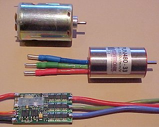
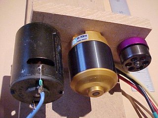
The picture above shows a standard 480 brushed motor (rear), an AXI 2820-10 brushless motor and a very small EFlypower do it yourself brushless motor.
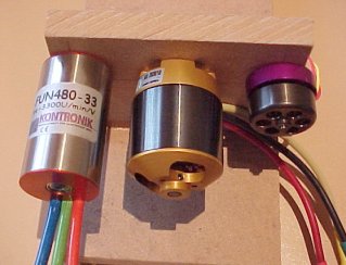
Another picture of the AXI (middle), EFlypower (right) and a Kontronic FUN480-33 (left).
The AXI and EFlypower motors are both "Outrunner" styles where multiple magnets spin inside a tubular iron sleeve around fixed Stator coils with a number of stationary windings, whereas the Kontronic motor has a spinning magnet inside a stationary multi winding stator. Therefore for water cooling the Kontronic style is much better as a coil of pipe can be wrapped around the motor body, however these motors are more expensive and have much higher speeds and lower torque than the outrunners so they generally also require a gearbox.
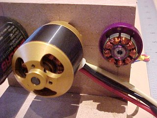
This picture shows the AXI motor and the EFlypower DIY motor with the outrunner magnetic rotor removed, I am planning on using 2 or 3 of these in the 1/35th scale Hull-2 boat off one controller, they are only 28mm diameter. If you are prepared to do some careful winding these are only USD$28.00 each and they are very potent little motors with 9 stator poles and 12 Neodymium magnets.
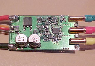
This is one of several Jia Bao 40A controllers I bought for the AXI motor (heat shrink cover removed for a look of course), the other side has 12 x N-channel Mosfets and uses a voltage doubling method to drive them, this controller is very small and very simple but quite cleverly designed and is based on a Silicon Laboratories C8051F331 processor and it seems to work great on the Kontronic, AXI and EFlypower motors. This JB 40A controller was only about USD$59.00 from EFlypower - an excellent price!
This is a Kontronic Smile 40-6-12 controller (heat shrink cover removed of course!) this has 18 mosfets and a heap of stuff on the other side that is under a glued on heatsink so further investigation is not possible (unless I blow it up). This controller will not operate the EFlypower motor or my home built electric Packard motor, starts but then shuts down, it does operate the AXI motor very well though.
The brushed motor in the background is just for size comparison. Kontronic is an expensive setup, I paid over $400 Australian (USD$300) for this pair!
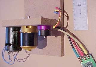
The ruler gives you some idea of the size of these motors.
Here is the AXI (middle) motor spinning, note that the rear and black parts rotate and the forward gold section remains stationary. Outrunner style motors have enormous torque and can drive very large airplane propellers without a gearbox. Cooling them is a bit of an issue though. The AXI 2820/10 is about the slowest in the range at about 1000 "rpm per volt" or so and is about USD$90.00.
Lets explain brushless motor "rpm per volt" figures: - If I connect the AXI motor (and controller) to a 6 cell - 7.2 Volt battery pack it will achieve a nominal maximum speed of around 7200 rpm and if I connect it to a 10 cell - 12V battery pack it will achieve a nominal maximum of 12,000 rpm, under load the speed will be less but it's a good way of estimating motor speed. It would be good if motors were measured in Watts output and efficiency but the only numbers that are available seem to be the number of Amps turning a certain sized airplane propeller, which I guess is trying to cater to the dominant use.
Any manufacturer that would like a motor or controller review just needs to send me a sample - note that this website gets in excess of 3.6 million hits a year currently!
I need a controller with reverse! Preferably a triple controller with a rudder mixer! may have to design one I suppose!
I am interested if anyone has developed any basic brushless and sensorless controller code for the 80C51, I'm great at electronic hardware, not so good at software.
A further word of caution, I am told reliably that Neodymium magnets can lose some, most, or all of their magnetism forever if taken over their curie temperature limit (which varies with price and quality of magnets, up to around 130 degrees C) so you need to keep them as cool as possible. So if you buy a second hand motor off EBay or somewhere else, you need a guarantee that they haven't been fried or they may well destroy your controller, motors need lots of magnetism to produce a back emf in order to limit the current flowing through the stator coils. If they have been fried they are most likely just three short circuits! Also some motors can achieve enormous speeds without load and can fly apart internally so always use them with a propeller attached.
This picture (above) shows the position and drive voltages to the coils (a large current flow is required in reality) required to turn a brushless motor using either a Delta or Y (Star) winding configuration, note that it is almost impossible to tell a Delta from a Y configuration on a motor unless you can see the centre join of the three windings somewhere and it doesn't particularly matter, the principles are much the same. As a particular stator pole is magnetically energised by current flowing one way or another - lets say North, it will attract a South magnet pole and repell a North magnet pole, the rotation that results comes from the most push or pull in a particular circular direction bearing in mind that they are really trying to push or pull outwards or inwards, but they can't, so they rotate sideways instead. In the case of this example the 12 magnets are polarised from the inside of the rotating ring to the outside and the inside polarity is shown in the picture above as it's the one which is reacting with the stator winding poles, the outside magnetic poles are all magnetically connected together by the ferrous metal outrunner ring. In this example poles 1,4 and 7 - (also 2,5 and 8) - (also 3,6 and 9) - are all wound together as one coil so that in this case there are 9 poles total but only three windings, so when pole 1 is magnetised North, so is pole 4 and pole 7. Motors vary in the number of poles and magnets, generally speaking more poles = more torque and less speed..
This is my drawing of the EFlypower motor (Apex 300 DD) - I am very impressed with this little motor so far.
This is my drawing of the AXI 2820 motor. If you want to you can screw a propeller adapter on to the three holes on the spinning part and make this the front, this generally makes it easy to replace a glow plug engine in a plane by bolting the stationary end to the firewall with an adapter bracket. I may use this feature to move air in the boat hull for cooling.
Just as a small aside, when I was the technical director of Dataplex P/L around 1990, I was sent a letter by the marketing guy's at Australian Magnet Technologies telling me all about their recent fantastic breakthrough's in super strong magnet technologies and seeking idea's as to what they could be used for, I promptly sent them a reply suggesting R/C model motors as one use. I received a thank you letter back stating that they were after serious suggestions! I don't know the current market size for brushless motors but it would have to be absolutely huge in the billions of dollars! I'd like to suggest, probably with great offence to some, that the reason that Taiwan, Korea and China have grown to become three of the greatest financial powers on the planet in such a short time is because they don't yet have a lot of marketing people!
I have tried the AXI 2820-10 brushless motor in Hull-2 in the swimming pool and at a small local pond and it has enormous grunt and can take a 40mm Raboesch propeller up to the point of cavitation and doesn't even get warm. so I have ordered two more of them and another Jia Bao 40A brushless controller to get the boat into the lake. I also tested one of the Hull-1 brushed motors in the direct driven hull-2 on a 40mm prop and it is not too shabby either!
Note that so far I have chosen and paid for all the items described on this page and I am not overly in favor of any particular motor or controller as they have not yet been fully tested in the boat, I am merely trying to further the brushless cause at this stage!
Late news, Castle Creations sent me a Barracuda-80 reversible brushless controller to review, thanks Shawn, see my review
I have bought a Hyperion "Emeter" from "aircraft.com" in Japan which looks like an awesome device for checking brushless (or brushed) motors, batteries and propeller (airplane) performance, we'll see what it does for boats! Hyperion also make a similar motor to the AXI 2820 with high temperature magnets and Japanese quality, I'll have to get one of those to try when the budget allows! They also make some nice looking brushless ESC's.
The Emeter has arrived and I am very impressed, I have tried most of it's functions in the charging / discharging of batteries as well as motor speed and current although trying to measure propeller rpm on the boat is a bit of a trick, some more thought required there. It's looking like I will mount an air moving propeller on the forward end of the outrunner motors for cooling the magnets and also measuring rpm..
28th June 2005, OK, using the Emeter and the new charger I have proven that my existing NiMH batteries are crap, maybe because I haven't used them for quite a while or maybe they're just crap, so I have invested in some GP3300 cells which I have put together as an 8 cell pack (9.6V) to compare against my existing 3 packs and as a 10 cell pack (12V) to see what I can get out of this beast.
Results from the static pool tests using the Emeter with an AXI 2820/10 motor direct driving a 40mm Raboesch 156-06 prop:
note: The Emeter adds an extra pair of Deans Ultra connectors and a 100A shunt.
Existing 3000mAH Batteries (8 cells, 9.6V pack)
7.40 Volts, 16.6 Amps, 8030 RPM (40mm prop) = 123 Watts, Total circuit effective resistance = 445 mOhms
These cells are connected with the existing tags that they came with which are probably nickel plated steel, I measured 60mV across them at about 8 Amps, so that's about 0.87V lost at 16.6 Amps or 14.5 watts wasted! and accounts for 52 mOhms of the total circuit resistance.
July 19 2005 I have added a sturdy 50Kg digital fishing scale to the arsenal and measured the forward thrust with the boat held stationary in the middle of the pool, held back by very strong mono filament nylon string and the fishing scale. With just the centre AXI motor and a 40mm 156-06 prop, Kontronic 40A controller, old 3000mAH 9.6V battery and no Emeter in circuit and measured 1.1Kg of thrust.
New GP 3300mAH Battery (8 cells, 9.6V pack)
9.58 Volts, 25.5 Amps, 9360 RPM (40mm prop) = 244 Watts, Total circuit effective resistance = 375 mOhms
That's double the power output! These new cells are connected with 7 short lengths of Deans Ultra 12g wire, directly soldered to the cells, I need to get some Deans copper connecting bars (and also a bigger soldering iron), or I need a pack with cells butted end to end to reduce the resistance even further. At 25 Amps we are still coasting (electrically speaking), and I also need a scale to measure the static thrust, it is many pounds!
New GP 3300mAH Battery (10 cells, 12V pack)
10.76 Volts, 30.0 Amps, 10,030 RPM (40mm prop) = 323 Watts, Total circuit effective resistance = 358 mOhms
These cells are connected with 12g Deans Ultra wire, again I need to get some Deans connecting bars, or I need a pack with cells butted end to end to reduce the resistance even further. So 3 of these and no Emeter in circuit and we are probably looking at around 1KW or 1.3 HP, excellent!
July 19 2005 I measured the forward thrust with the boat held stationary in the pool with just the centre AXI motor and 40mm 156-06 prop, Kontronic controller, new 12V 3300mAH battery and no Emeter in circuit and measured 2.4Kg.
I also tried all three AXI motors two with Jia Bao controllers and old 9.6V batteries and the centre AXI with the Kontronic controller and the new 12V battery, all with same props and measured 4.8Kg total thrust.
Currently I am waiting for some Deans connecting bars (ebay) and 20 more new 3300mAH cells! might also try making up a 12 cell battery although that is likely to exceed the current rating of the speed controllers, particularly if I hold the boat stationary. What does the current drop to when running at speed. Where is the Castle Creations 80A controller, lost in the mail it seems!
NEW July 23rd, 2005, New GP 3300mAH Battery (12 cells, 14.4V pack)
13.43 Volts, 42.1 Amps, 12,620 RPM (40mm prop) = 566 Watts, Total circuit effective resistance = 319 mOhms
This 12 cell battery is connected with Deans Battery Bars (Probar2.0) and only just tips over 40A for a short period with a fully trickle charged battery so it's probably safe to try the Kontronic controller at this current and I will definitely try the Jia Bao's. So 3 of these running and no Emeter in circuit and we are probably looking at around 1.75 KW or 2.3 HP total motor input, excellent! There seems to be no sign of cavitation at this speed (but I do have only one prop running) and the rooster tail with just one motor is like the picture on the main page which had all three motors running on the old 9.6V 3000mAH crappy batteries. The AXI motor is getting warm at this speed but the CC controller is just barely warm.
I measured the forward thrust with the boat held stationary in the pool, again with just the centre AXI motor and a 40mm 156-06 Raboesch prop, the new Castle Creations Barracuda 80A reversible controller, the new 14.4V GP 3300mAH battery and WITH the Emeter in circuit and measured 3.82Kg. Without the Emeter and a good re-charge = 4.3 Kg!
All I can say is wow! and where are my new GP3300 cells! I want to try all three motors running 12 cells.
12 cell battery packs are probably not a motor lifetime enhancing solution as the motors will probably cook at this sort of wattage, I am merely awestruck by the performance and seeing how far I can push it! Unless you can afford lots of motors, maybe stick to 10 cells! It could also be worth trying a smaller prop with this configuration.
The other thing that is necessary in trying to work out the boats performance is it's mass (static weight), i.e. how much are we trying to push and lift in the water.
Hull-2 without it's deck, superstructure, weapons and crew but with 30 NiMH cells, 3 motors and all the running gear it weighed in at 4.44Kg (9.76 lbs).
With the new laser cut deck fitted and three lots of 12 cell GP3300 battery packs, plus new battery boxes, receiver, 3x AXI motors and 3x speed controllers Hull-2 weighs in at 4.94 Kg (10.87 lbs). The latest pool test November 12th 2005 with 3x three bladed original looking 40mm props gave us a static pull thrust of 11.08 Kg (24.37 lbs) and with one motor/prop only (didn't seem to matter which one) 4.3Kg which is consistent with my previous tests. The Jia Bao controllers are getting fairly hot but they are running near or just over their maximum 40A current but the AXI motors and the Castle Creations speed controller are still not working up much of a sweat!
Hull-1 fully equipped and complete with brass cannons, brass rocket launchers, 4 torpedoes, batteries, motors and crew weighs in at 7.44Kg (16.36 lbs), ooh, that's more than I would have thought but Hull-1 has much thicker ribs, much longer prop shafts, heavier motors, a gearbox and a lot of brass and solder so Hull-2 is not going to be as heavy as that.
The original late war Elco 80' boat weighed in at around 50 Tons and (if these were US Shipping Tons then) that makes 56.63 metric Tonnes which if divided by 8000 ( = 20 x 20 x 20 or the scale cubed) this works out to 7.079 Kg (or 15.57 lbs). From the Elco movie "Devil Boats" we are told that the completed hull without deck or engines etc. weighs in at 12 Tons.
They also used 3 x 1500 hp engines and if we divide 4500 hp by 8000 we get 0.5625 hp and we are way ahead of that!
The model airplane guy's say, as a rule of thumb, that if a plane has as much thrust as its static weight, or mass, then it will fly very well, I don't know if we can say the same for a boat, because boats don't sink if you stop pushing them (well maybe they do stop planing and sink back into their static displacement position in the water), but it is a good starting point!
To get the boat 'up on plane' or 'on the step' it needs to be lifted up at least partly out of the water, so we do need to be able to lift it's static weight? Ken Nissen (Packard page) tells of the original boats sometimes being fully clear of the water. A good definition of planing is a boats ability at speed to displace less water than it's static weight or mass when stationary.
And therefore does it then become a reasonable proposition to assume that if we have enough horse power to generate a 1-1 thrust to mass ratio that if we have any spare power we should use it with an increased prop pitch to increase the speed?
Formula's for later
Horsepower vs Watts
1 Horsepower (550 ft-lb per second) = 745 Watts
1 Metric horsepower (542.5 ft-lb per second) = 735 Watts
-----------------------------------------
Torque and Horsepower
Torque varies directly with power and inversely with rotating speed of the shaft, or
T = K P / N
where T = torque in inch pounds, P = horsepower, N = revolutions / minute, and K = 63 000 (a constant)
Momentum = MVsquared
where M = mass and V= velocity
Another really simplistic way of measuring performance, lets say that the perfect model propeller has a diameter of 40mm and an assumed pitch of 1, which means that for every revolution it tries to move forwards through the water 40mm (or 4cm), or conversely if the boat is held stationary it tries to push a 40mm diameter column of water backwards by a distance of 40mm. the overall area covered by the prop is 20 (radius) x 20 (radius) x 3.1418 (pi) or 1256.72 square millimetres, take away the hub, say the 6.72, so lets say 1250 square millimetres x 40mm (pitch) = 50,000 cubic millimetres (or 50 cubic centimetres). 1000cc equals 1 Litre and 1 Litre of water (at sea level etc etc) weighs 1Kilogram (Kg). Therefore for every 20 revolutions the prop is trying to move 20 x 50cc or 1Kg of water 800 mm (pitch x 20) distance.
Therefore at 8,000 rpm the prop is theoretically trying to move 400 Kg of water at 320 Metres per minute, and this is only one propeller. More propellers doesn't increase the maximum theoretical speed, just the ability to push more water (or boat) at that speed.
Also therefore at 10,000 rpm the prop is theoretically trying to move 500 Kg of water at 400 Metres per minute. This is 25% more weight at 25% more speed.
Of course this method ignores efficiency, drag, velocity and a host of other factors but may be a rough ballpark calculation method!
| Mass (weight) of water | ||
| Pounds | Kilograms | |
| Cubic cm | 0.002205 | 0.001 |
| Cubic inch | 0.036127 | 0.0163871 |
| Litre | 2.204684 | 1.0000 |
| US Gallon | 8.345404 | 3.7854118 |
| Cubic foot | 62.42796 | 28.316847 |
Tons (US Shipping) = 40 cu feet (from above table this would seem to be 2497 pounds of water not 2240 lbs)
Ton (long) 2240 lbs = 1.016 metric Tonnes (1000 Kg or 1000 litres of fresh water at sea level)
| SPEED CONVERSIONS - KNOTS, MPH, FPM, KPH, MPM | ||||
|---|---|---|---|---|
| Knots | Miles per Hour | Feet per Minute | Kilometres per Hour | Metres per Minute |
| 1 | 1.152 | 101.37 | 1.85 | 30.92 |
| 5 | 5.758 | 506.70 | 9.26 | 154.58 |
| 10 | 11.515 | 1013.32 | 18.55 | 309.17 |
| 40 | 46.06 | 4053.28 | 74.2 | 1236.67 |
1 Knot = 1 Nautical Mile per hour
1 Nautical mile = 6076.12 ft. = 1852 m (1 degree of Latitude at the Equator) (1 Statute (land) mile = 1760 yards = 5280 feet)
So let's have a comparison with the full sized version of the original Elco propeller which has a diameter of 28" or 71.12cm and a pitch of 1, which means that for every revolution it tries to move forwards through the water 71.12cm, or conversely if the boat is held stationary it tries to push a 71.12cm diameter column of water backwards 71.12cm. the overall area of the column of water covered by the prop is 35.56 (rad) x 35.56 (rad) x 3.1418 (pi) or 397.28 square centimetres, take away the hub, say the 47.28 sq cm (75mm dia) so lets say 350 square centimeters x 71.12cm (pitch) for each revolution = 24892 cubic centimeters (or cc). 1,000,000cc (or 1 cu Metre) of water weighs 1 metric Tonne (or 1000Kilogram (Kg)). Therefore to move 1 metric Tonne of water we need 40.17 revolutions of the prop (1,000,000 / 24892) and theoretically that will move it 28.57 Metres (71.12cm pitch x 40.17 revolutions).
Therefore at 2,500 rpm the prop is trying to move 62.23 metric Tonnes of water 1778 Metres every minute. We have three props and they are all turning at the same speed so our upper speed limit is still the same at 1778 Metres per minute or about 57 knots and we can theoretically move 186.69 metric Tonnes of water (or boat)
If a US Shipping Ton is equivalent to 40 cu feet of water it would weigh 28.316847Kg x 40 or 1.1326738 Metric Tonnes so our 186 metric tonnes would seem to equal 164 US Shipping Tons.
So our theoretical speed is 57 knots (42% better than 40 knots) and with our theoretical ability to push a 164 Ton vessel (328% better than 50 Tons).
Again this method ignores efficiency, drag, velocity and a host of other factors but this does seem to be a rough ballpark method!
This is not as close as I thought it would work out! 42% slip and 328% drag so lets allow for the actual blade area instead.
So using the fairly accurate blade area of the original prop of say 243 square centimeters x 71.12cm (pitch) for each revolution = 17282 cubic centimeters (or cc) displacement. Therefore to move 1 metric Tonne of water we need 57.86 revolutions of the prop (1,000,000 / 17282). At 2500 rpm we would move 43.2 metric Tonnes per prop or 129 metric Tonnes total or 114 US Shipping Tons at the same speed as before of 57 Knots. This is closer but still more than 200% out on drag.
I would welcome any dissent or any other easy performance estimation methods that don't require Einsteins theories, anyway I preferred Leonardo, he drew pictures!
Can anyone confirm that the original boats displacement would have been measured in US Shipping Tons = 40 cu feet?
A New rudder mixer and speed controller driver (revised and now actually works!).
I now have a mix of a single reversible Castle Creations brushless controller and two Jia Bao forward only brushless controllers and unfortunately they have their neutral throttle positions at different transmitter throttle stick positions, so to overcome this issue I made up a small timer circuit to crop the first half a millisecond or so off the servo signal to the Jia Bao controllers so the servo signal pulse becomes permanently shorter and therefore their neutral location can adjust to become mid stick position same as the CC controller. Of course you could do this with a more expensive radio setup if you wanted but the idea of shortening the receiver pulse also lends itself to a stand alone rudder mixer circuit for existing speed controllers, if you add the same mixer circuit as used in the non brushless controller that I designed in 2004 and use a couple of channels of this delay timer, one for each wing motor..
Revised circuit 74HCT00 instead of 74HCT02
The 'Neutral Adjust' potentiometer lets you set the amount of time added to (or cropped from) the receiver throttle pulse. I have shown three output connectors one for each speed controller. I currently have only one of these timer circuits connected to two Jia Bao controllers with no rudder mixing at this stage just to get Hull-2 in the water for fast performance testing. As you can see from the 'threshold' waveform (U2 pin 6) the pulse width can be varied by two different methods at the same time, either the charge rate (rise time or time constant) of C5 & R9, VR1 can be set by the 'neutral adjust' pot or it can be simultaneously varied by raising or lowering the 2/3VCC threshold voltage on pin 5 of the 555 cmos timer (U2). Using two of these circuits and the rudder mixer circuit from the "electrics" page we can raise the threshold voltage on one wing channel and therefore increase the extended (or cropped) time and lower the threshold voltage and shorten the extended (or cropped) time on the other wing channel, effectively moving the neutral stick position to the two wing speed controllers. We do need reverse on the wing motor controllers for this to work effectively and give us great manuoverability though!
I am intending to add the rectifier diode's (D2) shown from output connector pin 2 from all three speed controller BEC circuits so that whichever of the three battery packs has any voltage left can still power this circuit and the receiver and servo's in front of it, this also allows us to leave the three controller BEC wires in place in their connectors without causing any damage. These rectifiers should be Shottky types to reduce the voltage drop to about 0.2V and they need a current rating larger than the BEC current rating.
The revised circuit is shown as a pulse width extender where the 555 timer pulse output time is added to the original receiver pulse time. I have also shown three dotted lines and three "x" line removals if you want to shorten the pulse length instead, in which case the 555 pulse is triggered by the front rising edge of the servo signal input and the output pulse is this 555 pulse width subtracted from the original.
You can build three identical circuits like this or connect the center motor output signal directly to the input signal, depends if you need adjustment for the center speed controller neutral or not.
Another related thought I had was that this circuit along with the same rudder mixer signals could also be used to vary the original rudder signal feeds to three separate servo's controlling the boats three rudders and then we could help the port and starboard rudders track a smaller or larger radius when turning in each direction. This would also give us a higher rudder torque load rating using three less expensive servo's and potentially increase our efficiency and maybe also our top speed. Three servo's would also simplify the rudder linkages. Hmm!
Motors for the Schnellboot - 2014
I have purchased three brushless motors for the S-Boat model
and 3 brushless motor speed controllers from Hobbyking.com (China / Hong Kong),
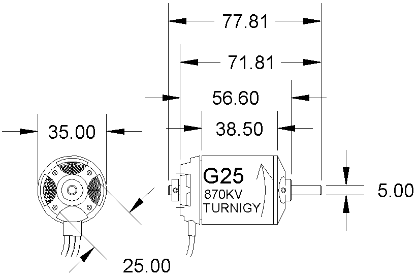
These are Turnigy G25 motors: Turnigy G25 Brushless Outrunner 870kv
AUD$26.50 and HobbyKing 120A Boat ESC 4A UBEC AUD$49.26. These Motors are around
10mm longer than the AXI motors that I used in the Hull-2 model.
The Schnellboot Hull is quite a bit longer than the Hull-2 hull and is a deep hull, not a planing hull and it will have 50mm diameter props rather than 35mm diameter props, so it needs a lot more power.
However disappointingly these motors have their output shaft coming out of the spinning end rather than at the fixed end, great for mounting on an airplanes bulkhead but not so good for boats, they would need to be mounted on the prop side of the motor mount, I may have to ditch these and go for a bigger version of the AXI motors which work really well in the Hull-2 model - I was not expecting this - I was looking for a more economical motor!
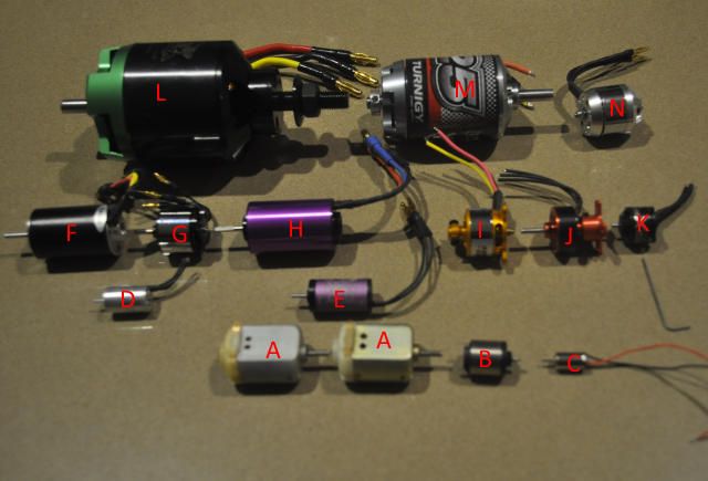
Above is a collection of brushless (D-N) and small brushed motors (A-C). The purpose of this collection is to show the large range of sizes available. Motor L is being used in the Scnellboot 20th scale hull. Motor A (brushed) is used in the 20th scale Mk13 torpedo and I need a motor for the Schnellboot torpedo, the main contenders being F or H as these are a perfect diameter and both inrunner motors so the outer body can be fixed to the printed circuit board and don't require any clearance.
2019 - 3Amp ESC
Below is my version of the circuit diagram and the PCB layout for one of the single LiPO cell, 3Amp ESC's that I have used in my 35th scale torpedo, this ESC is tiny! 13mm (1/2") long x 10.5mm (7/16") wide and is based on a Silicon Labs F330 (8051) micro processor. I have three other ESC's all based on this or a very similar design to this one, all based on the same Silicon Labs processor and these use a variety of processor firmware code but the BLHeli firmware can be downloaded from various sources and these processors can be "flashed" to update the code. There is a list of links below.
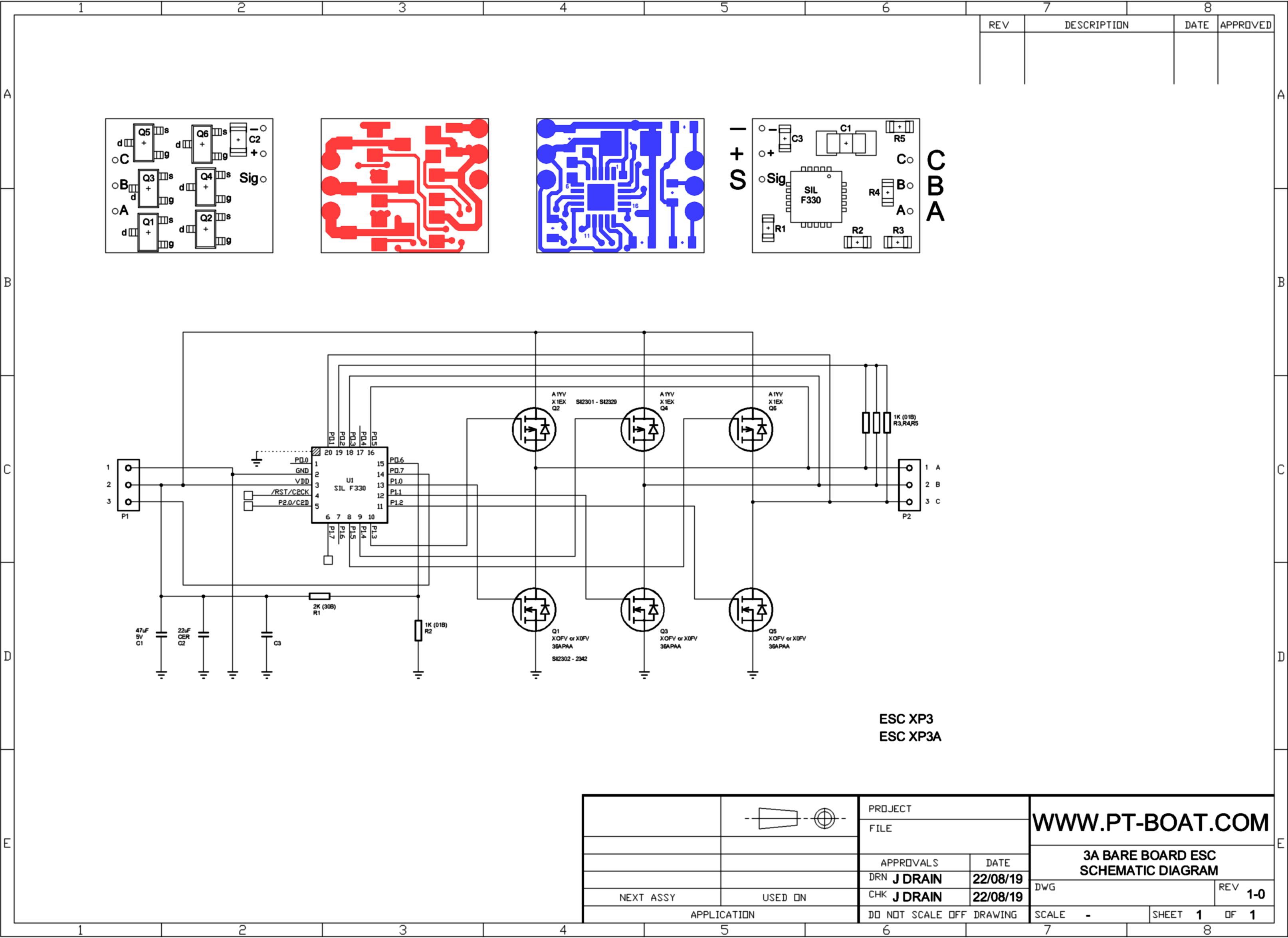
Click here or on the picture to download a larger version.
The drawing and PCB layout was done in Autocad and if you want a copy of the DWG file or a DXF file just ask. The PCB layout has solder masks for both sides and a drill detail layer
For more info on the BLHeli code and flashing see:
https://github.com/bitdump/BLHeli
https://www.helifreak.com/blogs/4712
I'm not suggesting that we should attempt to make this tiny speed controller, they are under $20 to buy, so that would be silly but I just needed to understand it and have the design available for my torpedo's in case they cease to be available!