The Rudders
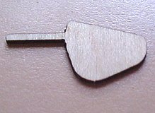
I redrew the left rudder picture (below) from a copy of an original Elco rudder that I bought from www.ptboats.org, it is correct for early Elco boats up to PT102 but it is not the correct shape for the 80' long PT103 class boats which had a more elliptical rounded shape. I haven't been able to find a drawing (yet) for the PT103 class rudder except for outline drawings as shown on parts of other drawings, so using those as a general shape guide I have drawn the right hand "rounded" rudder and the 2nd picture below which should be fairly close. The rounder rudder shape tends to move the point of maximum blade thickness closer to the line of the shaft and there is also more "meat" in front of the shaft pivot line and less behind it which makes some sense given the increases in horsepower for the later boats which would have made the original rudder increasingly harder to turn. Also the shape was probably easier to make at a time when production ease and speed was more important.
One other possible reason for the change of shape, that came to light recently, that I hadn't considered, was that at high speed the rudder, like the propeller, also has cavitation problems and making the rudder elliptical with no sharp corners or straight lines apparently reduces cavitation. (cavitation is where the water loses contact with the rudder due to a vacuum being formed).
The red lines show the rudder blade thickness at any particular point. The dimensions shown may not be correct for the PT103 class, it also seems that the shafts may have been longer on the later model???
The centre rudder shaft was longer than the port and starboard rudder shafts so that the linkages between them were in line horizontally.
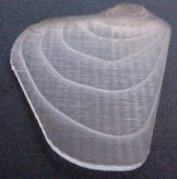
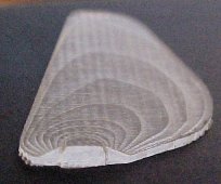
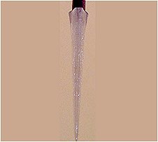
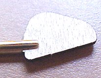
So, armed with the above drawings and the laser cutter and my success with machine gun etching I thought I would try to make a rudder the same way, so using the blade thickness and outline autocad data I produced a series of 16 equal thickness etching mask patterns and cut the following half rudder out of 3mm acrylic sheet. This rudder half is about 1" or 25mm high and varies from 3mm thick at the top to 0.6mm thick at the bottom with 0.2mm steps. So I need to make the other side and then sand off the steps and I will have a master for casting.
 Strut and Rudder
 Rudder thickness
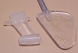
These pictures show the newly laser engraved and finished acrylic masters of the rudder and rear propeller shaft strut that the propeller pushes against, the blotches in the rudder are where the two acrylic halves are glued together, the finish is highly polished! I have made the rudder 50% larger than scale with a 4mm shaft and I have made the strut with a larger than scale bearing that is the same diameter as the Raboesch propeller hub (8mm) and to take a 4mm diameter (5/32") "standard size" prop shaft.
At true scale the shaft should be 2.54mm diameter and short of casting my own propellers I cannot easily use a shaft that size and I have serious doubts about it's stability or strength at such a small diameter when driven hard by big brushless motors, likewise the rudders at true scale are so small compared to the ones on hull-1 that they would be next to useless I think.
These masters were cast at Apec Investment Casting and made out of Silicon Bronze.
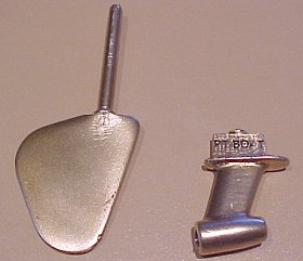
Tah dah...
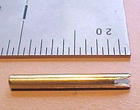
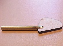
These are great, they need cleaning up and polishing a bit but I am very pleased, the shaft on the rudder is just a smidge under 4mm diameter and came out pretty round but I will put a section of K&S metals 3/16" thick walled tubing over it and solder it in place and then it will fit in a standard Radio Active MA 3062 Mini Rudder fitting. The strut bore is also just a smidge under 4mm diameter so it can be drilled or reamed out to fit a standard 4mm or 5/32" propshaft.
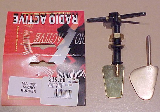
Radio Active small rudder, available as different brands around the world. There are a couple of different sized blades (which would be a good shape for a Higgins PT Boat) but the shafts are all the same size 3/16", I used these on boat-1 and I have never had a leaking rudder, they seal really well, so if it aint broke!.
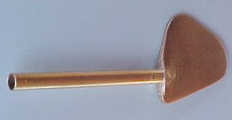
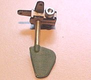
This is the rudder with a length of 3/16" thick walled K&S brass tube soldered on, I used some good flux as the silicon bronze can be hard to "wet" and covered the rudder pin with a thin tinned coating of 60/40 solder using a soldering iron and then fitted the tube over and heated it upright in a vice with a (very) hot air gun (paint stripper) with some extra solder added from the top of the tube until the solder melted and then flowed neatly around the top of the propeller part. You could probably roughen up the inside of the tube and use an epoxy glue as an alternative to soldering, the pin is quite long and a bit rough from being cast anyway, it could also be drilled through and pinned.
Many fast racing boats have a small hole drilled in the front edge of the rudder and up through the shaft as a source of cooling water, these rudders are thick enough at the top to try that method.
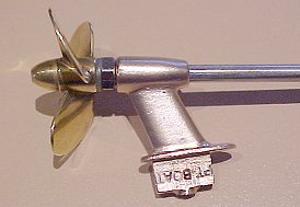
Here is a strut drilled out to 4mm and a prop shaft fitted (hard metal + high speed = blunt drill!). The nut spoils the look and could be replaced by some anaerobic glue maybe (or locktite) as the thread is a normal right hand thread, the opposite hand propeller is not technically correct but could be a good idea as it would tighten when going forwards, depending where you live mine is a left hand propeller, which is correct for true Elco scale but will unscrew going forwards unless locked with a nut or glue. I have never tested the idea of having the centre prop going in the opposite direction to the outside props but it has been suggested many times, it's just not scale but I will try it one day!
Rear Strut layer drawing with the correct scale size bearing and 2" propshaft
I have already started on and will also do the other strut for the forward end of the propeller shaft just aft of where it leaves the hull but that can be fitted later, at the moment though I am trying to get hull-2 in the water and keep up with the needs of the hull-2 kit builders....
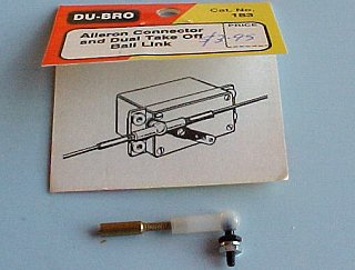
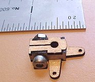
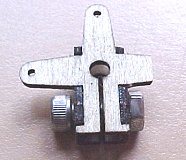
These airplane aileron ball links are a great idea for coupling the rudder tiller arms together, especially in hull-2 as the rudder shafts are not parallel so any fixed wire method will probably bind, there is a single and a double for the middle rudder and they are usually joined with small threaded wire so the distance between them can be easily adjusted.
Basic Rudder Linkage setup using simple wires, better if you use the ball joints above but this has worked in Hull-1 for many years.
The 1/35th Scale Hull-2 Rudders
For the 1/35th scale hull I decided to make some rudders completely as I couldn't find anything small enough to suit the scale so I cut out the rudder blades from 1.2mm marine ply on the laser and then glued them into a 3mm diameter (OD) shaft (2mmID).
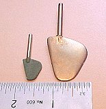
The 1/20th cast silicon bronze rudder with the new 1/35th ply rudder side by side.
File out a slot in the bottom of a 3mm OD brass tube rudder shaft and make it tapered so that it can be squeezed onto the rudder blade to add strength and then glue it in place with medium superglue. Then give the blade a bit of a sand to shape and paint it with a couple of coats of oil based paint.
I then needed to make a suitable Tiller Arm to go on top of the 3mm rudder shaft so that it could be turned by the steering servo. Again I made this from 1.2mm marine ply out of 4 pieces and glued on an M3 nut and used a 8mm long M3 hex head screw to provide the clamp onto the shaft. It took me a few attempts to get something that was reasonably easy to put together and worked as I wanted it.
I glued 3 x 1/2" lengths of 4mm (OD, 3mm ID) K&S brass tubing through the hull main keel and the two rudder keels, just protruding below the planking, so that the rudders fit up through from the bottom and the tiller arm attaches to the top of the rudder shaft and holds it in place. Once finished and all painted I need to grease the shafts to prevent water from soaking up the tubes but I need to make sure that the grease does not get around the tiller arm or it will not clamp tightly enough and it will slip, so I will put the rudders part way into the shafts first and then apply the grease to the lower part of the rudder shaft.
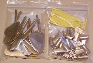
I will add these parts to the 1/35th Hull-2 skeleton kit. Anybody building the 1/35th Hull-2 kit that hasn't already found or made something should ask me for a set of laser cut parts and I will make them up separately.
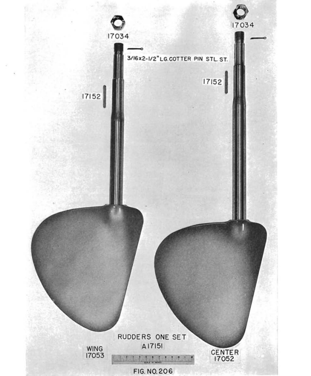
I recently found an original photo of the original PT103 style rudders, you will notice that the centre rudder does indeed have a longer shaft. The aft profile edge of the blade is more rounded than I had assumed but I am fairly accurate on the rest of it.
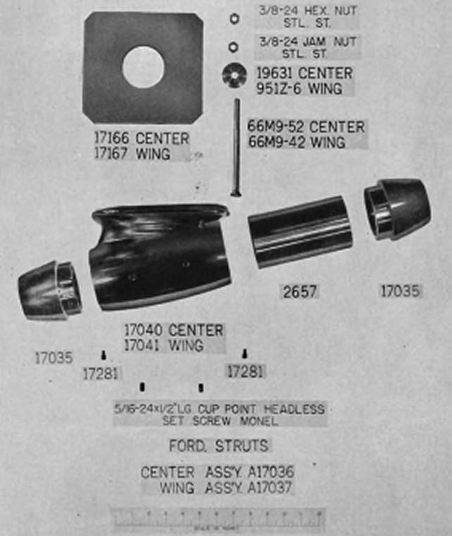
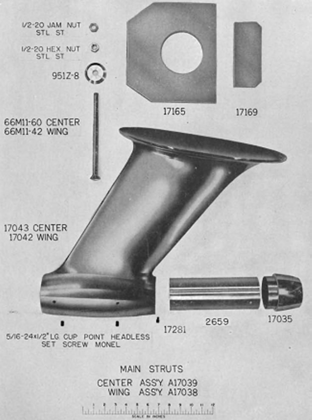
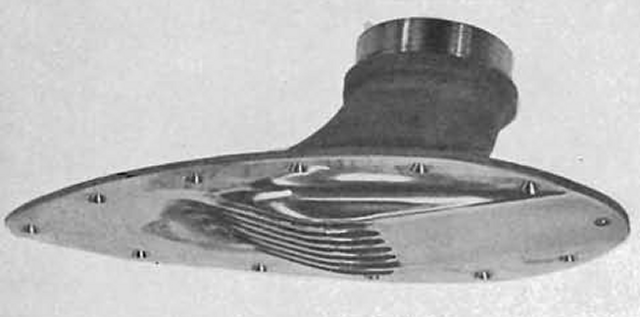
I also found photo's of the original main and forward struts.
This is the salt water scoop that picks up water for the engine cooling system.