Packard V12 Marine Engine
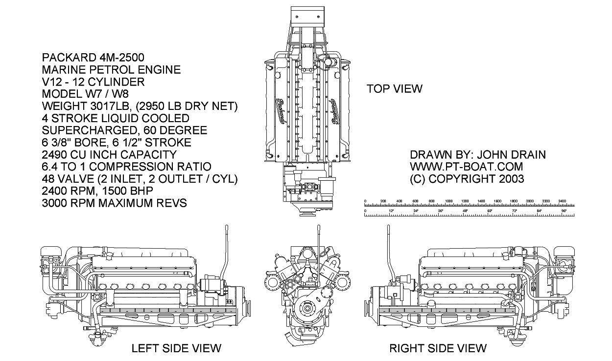
The modelling objective here is to make an operational 1/20th scale Packard V12 Marine Engine that looks like the original V12 engine but is actually an electric motor (and possibly gearbox) housed in a cast shell and when completed it should fit the exact mounting bed of the original engine.
Contrary to popular belief the Packard V12 4M-2500 marine petrol engine did not start it's life as a licence built US made copy of the British Rolls Royce Merlin engine, this has been pointed out to me by various people and the historical evidence proves this, the Packard V12 1M 2500 engine was used extensively by Garr Wood in his world record holding speed boats of the 1930's and the licence built Merlins were not produced by Packard until well into the war years.
"Despite the commonplace assumption, the new-generation Packard marine engine, initially tagged the 4M-2500, was anything but a re-popped Liberty. Instead, Vincent, Packards lead engineer, started with a clean sheet and designed a four-stroke, 60-degree V-12 with an aluminum block with a bore of 6.04 inches and a 6.50-inch stroke, which brought it to 2,490 cubic inches. Weighing 2,900 pounds, the 4M-2500 had four valves per cylinder, a 6.4:1 compression ratio, and a centrifugal supercharger, later models were also fitted with an intercooler. A Holley 1685F aircraft carburetor supplied the fuel, 100-octane gasoline, fired by two spark plugs per cylinder. The first engines developed 1,200hp, but improved versions with higher boost levels nominally made 1,500hp. Packard built 14,000 marine engines during the war, three of which went into each of the Navy's 768 PT boats, two astern and one amidships for better service access. "
see: http://www.hemmings.com/hcc/stories/2006/01/01/hmn_feature17.html
Packard built many thousands of engines prior to the second world war including car engines, of course, and the famous "Liberty" aircraft engines and Packard's own developments and patents and other developments and inventions by the likes of General Electric on superchargers went into the development of the Packard marine engine that were produced in their thousands during the war to power the U.S. Elco and Higgins PT Boats and the British Vosper MTB's (Motor Torpedo Boats).
The Packard 4M 2500 engine powered most, if not all, of the US built PT Boats. The pre and early world war II engines developed some 1200 brake horse power, this had been increased to 1350 BHP and then by the end of the war 1500 BHP, therefore a late war Elco 80' PT had three engines producing a total of 4,500 brake horse power and could guzzle 5000 gallons of 100 octane aviation fuel in one night of operations. The cruising speed of the Packard was stated as 2400 rpm but note that the Elco "dashboard" tachometers show a top speed of 3000 rpm. I assume that this means that the top speed of the Elco at some 41 knots could only be sustained for a relatively short period of time.
I'm told that some crews upgraded the engines in the field by changing the gear ratio's on the supercharger impeller, increasing the engines horsepower but making them quite temperamental.
Packard made a three terminal electrical device to synchronise the three engines. I am trying to find out more about how that worked.
The centre engine faced aft and drove the centre prop shaft directly, whereas the port and starboard wing engines faced foward and drove into a Veedrivegearbox which then drove the wing propshafts back down under each engines. note: that all three propellers turned the same way, clockwise looking from aft.
The Model Begins: Aug 2004
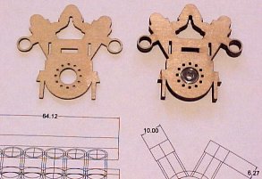
One of my first idea's was to laser cut all the parts for a neodymium magnet based crankshaft, 6 sets of coil 'C' cores which fit in the engine "pot" area and other bits and pieces out of Silicon steel transformer lamination material but when I got the quote for laser cutting the 400 odd pieces at about $1 per piece to make one experimental motor I quickly changed my mind, I am getting the crankshaft parts cut though as I have no choice with those.
The motor end pieces shown above were cut out of 1/16" (1.6mm) marine ply as part of a test of a few of the new laser cut ribs for boat 2. The detail is amazing, I didn't expect them to come out so well, the rings are only 1mm wide and I must say from past experience I expected them to burn off. These ply parts were cut for me by Jordan Buhagiar at Alfex CNC in Melbourne using an Epilog Mini 50 watt CO2 desktop laser cutter, I want one of those!
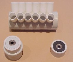
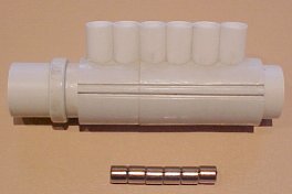
So this is the new lower cost engine plan, these two pictures show the PVC / Styrene master so far. The main tube parts are 20mm electrical conduit and a couple of fittings glued together. The "pots" are 3/8" (9.5mm) styrene tube from the hobby shop. My intention is to resin cast the engine housing once it's finished. I have fitted 10mm x 3mm x 3mm ball bearings into the end pieces as the crankshaft bearings. The right hand picture shows 6 of the 1/4" Dia x 1/4" long neodymium magnets that I will be using for the crankshaft. The idea is that the crankshaft will have 24 of these magnets in 60 degree staggered sets of 4 and 12 electromagnet coils will be up in the "pots". This will make a 12 cycle per revolution motor which should give it tremendous torque. However I have another idea which I am also pursuing for a much simpler version. Rare earth Neodymium magnets are so strong it is recommended that you wear eye protection in case they snap together and shatter.
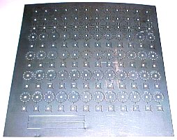
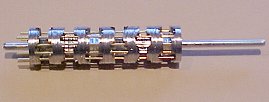
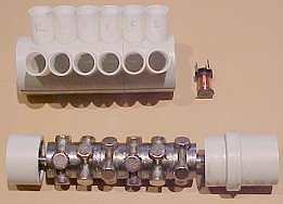
Here is the sheet of silicon steel crankshaft laminations which were laser cut, the assembled crankshaft (I used brass wires through holes to align the various sections) and then the right hand picture shows the finished crankshaft with magnets installed. I am intending to use some commercial ferrite coils (or chokes) for now, just to try out the idea, later I will make up some laser cut laminations and hand wind some better coils but so far so good!
Late War Packard models
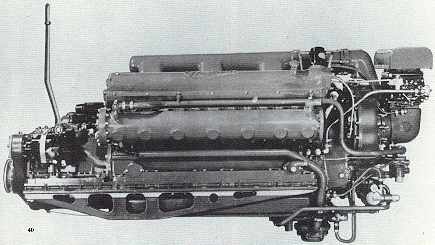
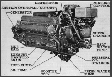
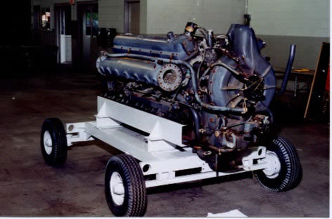
I Can't remember where I got this photo (below) from but I think it was a boat restoration project (great trolley).
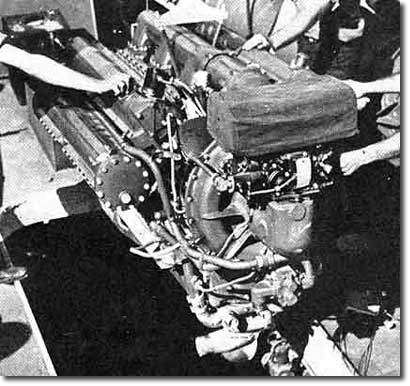
The pictures below show earlier versions of the Packard V12 engine, note the two bolted access panels on the side of each muffler rather than the "bumps" on the later mufflers..
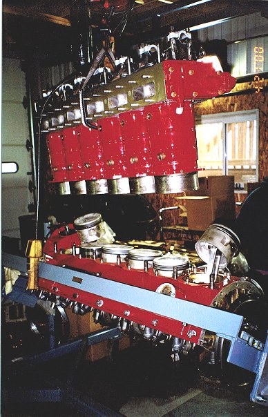
The photo's below are of an early war Packard engine restored by J and M Machine Co of Southborough, MA, USA, http://www.jandm-machine.com these photo's were sent to me by John and Michael of J and M.
So if you are looking for someone to restore your PT Boat engines, these guy's have the experience!
Look at the size of those pistons - 6 1/2" diameter
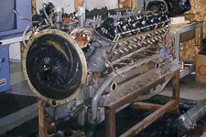
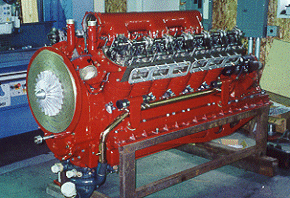
Before and after shots showing the supercharger impeller and all the clockwork.
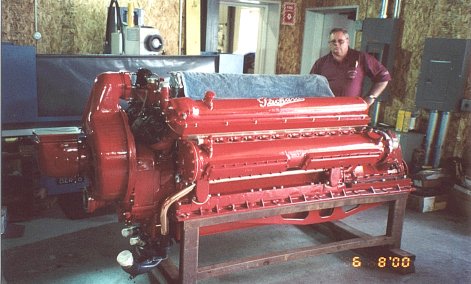
What a beast of an engine! the original engines were a boring grey colour, red looks so much better. This restored motor was apparently going into a pleasure craft - I'd imagine a fairly FAST pleasure craft!
A small history lesson told to me by Ken Nissen
You no doubt know that the Packards had an over speed cutout/off that stopped the engines somewhere between 2500 and 3000 rpm. We were all a bunch of 20 year old kids and pushing too hard in fairly rough water could bounce the boat out of the water hence the overspeed cutout. I have seen daylight under the hull of our companion boat many times. The other thing was that when we were on patrol we idled all night so when we started back to base all engines were running as fast as they would go for maybe 2 hours. We (engineers) never objected because this blew the carbon out of the engines. As fast as they would go was usually around 2200 rpm. They might have done better in a cooler climate, I don't know. This was sort of a race and the slower boat would get the lead boats rooster tail whipped over his bow and a resulting bath. Makes for a pissed off skipper and we would be down working on very hot engines the minute we tied up. These engines have dual ignition and if the two points were not in exact sync you ended up being the slow poat. Next time out the SOB in the other boat got the bath.
PACKARD 4M 2500 ENGINE (was) FOR SALE
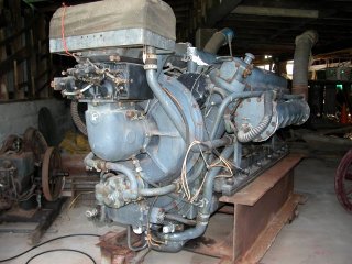
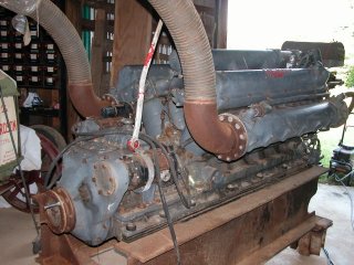
This engine WAS for sale, (now sold) it was built on Oct 19, 1943 and rebuilt at Norfolk in 1959.
According to the owner Robert A Stadler, it only ran for 5 minutes since it was rebuilt. He turns the engine over by hand twice a month and it has so much compression that he had to back out a set of plugs (these engines have two plugs per cylinder, two distributors etc) S/No: 8614
Robert was kind enough to send me these photo's which show some great detail.
I would like to have bought it, only it's in the US and I'm around the other side of the planet, so the freight would have been ridiculous.
Robert says he has drawings somewhere! Find them Robert.
Apparently this engine is now going into a Hackercraft.
